Thanks to 3D printing, most of us are familiar with the concept of additive manufacturing, and by extension, subtractive manufacturing. But what is it when you’re neither adding material nor taking it away to create something? Generally speaking, that’s called forming, and while there are tons of ways to do it, one you might not have heard of is single-point incremental forming (SPIF), and it’s pretty cool.
To explore SPIF as a method for making small parts, [Russell Makes] gave it a go on a small CNC mill. The idea is pretty simple, and the video below makes it pretty clear what’s going on. A forming tool is moved over a sheet metal blank that’s held very securely to the mill’s table. The tool has no cutting edges, just a smooth, hard, spherical tip — [Russell] made his own by brazing a carbide ball to a piece of drill rod. The tool is driven slightly into the blank along the Z-axis, while simultaneously tracing out a tool path in the XY plane. The tool spins, but very slowly; ideally, the spindle speed is controlled to keep a single point of contact with the metal as the tool works around its tool path. The tool steps downward incrementally, drawing the metal down with it as it forms the desired shape.
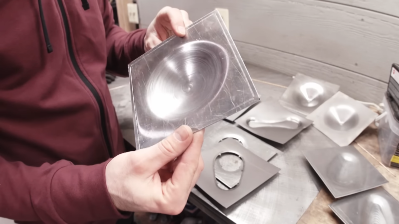
[Russell]’s experiments were pretty promising. He started with titanium sheet, which behaved pretty well except for some galling thanks to lack of lubrication. Aluminum and stainless worked pretty well too, at least for simple hemispherical and cone shapes. More complex shapes proved trickier, but with time he was able to figure out the correct speeds and feeds to keep the metal intact. The amount of tension built up in the metal is impressive, though, and is especially evident when cutting the finished part free from the blank.
Could this work with a hobbyist-grade machine? Possibly, but we’d be afraid that the forces involved might be a bit much for light-duty machines, especially in the Z-axis. And it’s a slow process, so it’s probably only good for one-offs and low-volume work. Once you’ve got a prototype, die stamping might be a more efficient way to go.


Would it help to make multiple passes to allow the metal to time to move and stretch and distribute the stress and minimize the heat?
Or, completely the other way, spin the tool faster to heat the workpiece locally? Kind of like flow-drilling but a little less aggressive.
I’m thinking multiple layers, complete each layer from the edge to the center, then repeat with a step in. That would eliminate any stress, as well as deform each layer a step at a time. Of course that will take many more passes, but the quality will improve due to repeated chaotic error.
There are a lot of issues with galling and work hardening here. If you had the equipment to do this with the metal heated to softness (for non-hot-short metals) that could work pretty well.
No, that won’t work. There is quite a lot of elasticity in steel, and it won’t permanently deform until you go over the maximum tensile stress limit, and then then you make a bit of permanent deformation. When the tool moves on, then the same tensile stress that is in the “elasticity part” is still present, and that wants pull it back towards the old form.
I can see two methods that do work. One is to deform the material more then the final form implies, so when the stress (due to the elasticity part) is released, your part has the correct form. There is a bunch of research going on in this direction.
The other way is a heat treatment. If you heat the steel enough, then it gets soft enough to relieve the internal stresses, and after cooling down it will then retain it’s shape. This is a well known and common method that is for example used after welding (which introduces high internal stresses) of precision constructions, such as a CNC machine.
Maybe annealing the workpiece will allow more aggressive machining.
Or anneal still in the jig after forming to release stresses? (Noobie thought)
That’s a good idea that would likely work out well.
This seems to be a video of a similar process.
https://m.youtube.com/watch?v=dCXu8Ju_fdY
I’d be happy if PCBway offered this and I could just order the prototypes. I don’t need it for hobby work in the house.
I think it was Destin of Smarter Every Day, that did a YouTube tour of a small plant that does SPIF machining. But the machines they used there had two points, one on either side of the work piece, which is a lot more precise than just pressing on one side. The two tools are offset from each other in the direction of the gradient of the desired surface at that point, and they press together to affect that point without affecting the rest of the piece, allowing for some pretty tight curves in the surface. Needless to say, there must be very, VERY little flexing of the machine in order to get that to work right.
They actually call that “roboforming”, because it uses two separate and very hunky robots, one on each side of the work piece. Prepare to have your mind blown: https://www.youtube.com/watch?v=dCXu8Ju_fdY
The insteresting part is near the end when he points out that to form a dome they first form a cone then push the cone into a dome shape to avoid having the material getting too thin near the edge.
It’s one of those things you wold not immediately think of but make sense that sometimes you go through an intermediate shape for best results, just like you do with normal metal and woodworking actually; albeit not for the exact same reason.
I’ve done some press forming and have to do it in a similar way, using progressive dies that stretch in specific areas so it doesn’t over-thin in one area. It’s really difficult to design a deep stretching process and end up with even close to uniform thickness!
its a shame he couldn’t make a “ball point pen” type tool instead of the fixed ball head. my silhouette cameo uses tools like that for embossing and if nothing else is leads to the wear being spread across the whole ball.
I think that would put too much wear for the tool that holds the ball. Even with plenty of lube it would eat away at the holder and deform it. And at pressure and speed, I’d hate to be in front of that when it pings out and embeds itself into the wall.
What your mom said…
There are a couple of finishing bits making the rounds on youtube right now, that are a hardened steel bearing backed up by a ball bearing race, so the hardened bearing is smashed into the workpiece and slightly planishes it, with the bearing supported by the race.
I’m wondering if you couldn’t do something like those giant (hundreds or thousands of kilogram) stone spheres that some places have as public art with a water supply pumping just a bit of water in so the whole thing’s running on a micro layer of water and you can spin it by hand. Imagine a hardened bearing ball running on a microfilm of oil the way internal combustion engine bearings work. Plus it would also reduce workpiece to tool galling.
Forming silver and pewter (Britannia metal) on a lathe, a technique often called “spinning” is another form of SPIF.
This Old Tony has a couple of good videos on that.
It’s a very under-appreciated technique used a hell of a lot in industrial production but you don’t see it DIY very often.
3003 aluminum works really well too. Still scary as anything when you’re starting a flat sheet that is only held between the chuck and tailstock by friction: that first sweep is either going to stick it to the form or fling it straight out into the room, a spinning thin disc of doom.
But once it’s going, it’s magic.
try thick or thin copper
Fascinating. Reminds me of spin forming in some respects (I think someone else mentioned that also). I didn’t watch it all the way through, but I think he’ll find that the wall thickness of his final parts is not uniform and its probably thinnest near the start of the forming zone. Cut them up radially and take a set of calipers to them to find out. The material flow during the forming and the corner stresses are going to determine the chance of success here. The curve of the “peanut” shape was too tight and too near the corners, causing too much strain and a material tear. Using larger blacks relative to the form shape and some tension in the sheet during the clamping (towards the perimeter) should help even out some of the unevenness of the stress on the material. Differing tool end radius for different shapes might help too, fewer passes would reduce accumulated work hardening, making forming stress lower and lower the chance of tearing (at least in theory). I hope he keeps working on this.