Hobby servos are great, but they’re in many ways not ideal for robotic applications. The good news is that [Adam] brings the latest version of his ServoProject, providing off-the-shelf servos with industrial-type motion control to allow for much, much tighter motion tracking than one would otherwise be limited to.
The PID control system in a typical hobby servo is very good at two things: moving to a new position quickly, and holding that position. This system is not very good at smooth motion, which is desirable in robotics along with more precise motion tracking.
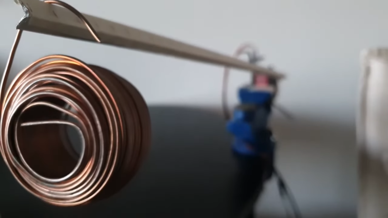
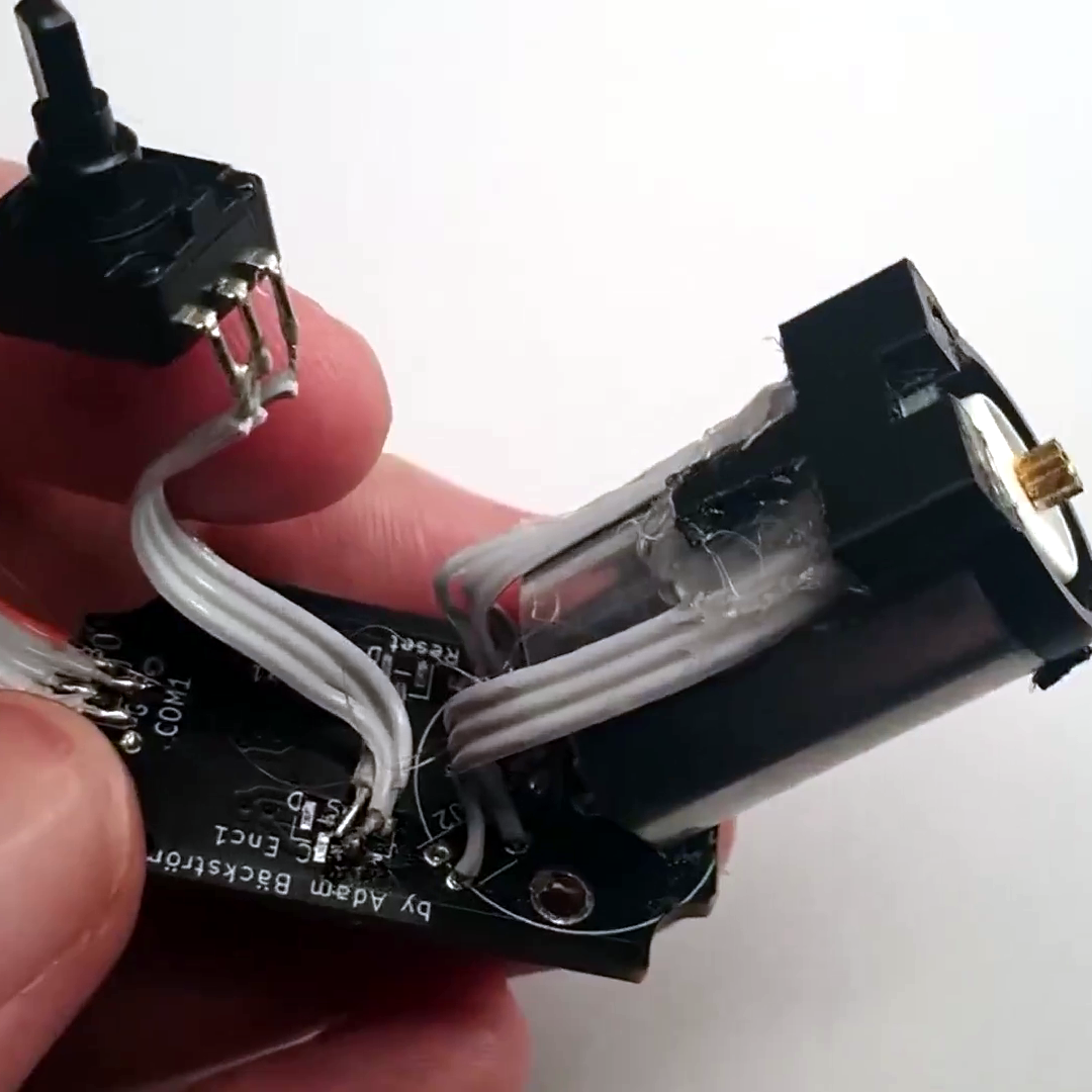
[Adam] has been working on replacing the PID control with a more capable cascade-based control scheme, which can even compensate for gearbox backlash by virtue of monitoring the output shaft and motor position separately. What’s really new in this latest version is that there is no longer any need to perform surgery on the DC motor when retrofitting a servo; the necessary sensing is now done externally. Check out the build instructions for details.
The video (embedded just below) briefly shows how a modified servo can perform compared to a stock one, and gives a good look at the modifications involved. There’s still careful assembly needed, but unlike the previous version there is no longer any need to actually open up and modify the DC motor, which is a great step forward.


WOW – I haven’t seen a project as good as this one in a while. This one is going places!
Amazing project. This is how Servos needs to be built at the first place. This is a major surgery too, but of a different kind bringing very different results to the table. Good job.
The reason why common servos are sloppy like that is because the control loop is “softer” – they don’t apply a lot of torque for small control movements. That’s for two reasons: noisy jittery signals over traditional analog radio would cause the servo to twitch around and consume a lot of power trying to keep up. Digital servos using 400-500 Hz signaling instead of 50-70 Hz exist, and they’re a lot more precise and powerful, but keeping that aggressive control consumes more power, eating up your batteries, and overheating the servo more easily.
Does anyone have a link to a diagram of a traditional analog hobby servo’s internal workings? What’s the circuit that decodes the control signal?
nowadays its 8 pin asic or very small microcontroller
Yep, but I’m interested in what the ASIC has inside.
The reason why the servo pulse is about 1.5 ms long is because it was designed to be multiplexed by a simple “divide by N” circuit that passes each subsequent pulse to a different output.
An earlier version that wasn’t designed that way used a simpler PWM scheme. The position sensor controls an oscillator with a variable duty cycle and subtracts that from the input signal duty cycle, so that when both are equal the sum is zero and the DC motor gets no power. When they’re not equal, the sum is either plus or minus 1 depending on which PWM signal is leading, so the motor gets a short “kick” in that direction. If the difference is small, the pulse width is narrow, and if you’re driving it all the way from one end to the other, it gets full 100% duty cycle that starts diminishing when as approaches the set position, which makes for a rudimentary proportional controller – but it means that your control signal takes up the entire channel and can’t be multiplexed.
The later version used some sort of pulse stretching scheme to “decode” the short millisecond blip into the 20 ms PWM signal cycle for the same effect, and I’d like to see how it was done.
For low power servos, the pulse was simply converted into a variable voltage and passed through a linear difference amplifier. For high power servos, the PWM scheme was used because the linear amplifier would burn up from being too inefficient.
To clarify: with the PWM scheme, when the servo receives the pulse, it triggers the position sensing oscillator that generates a single pulse with a width that corresponds to the servo position somewhere between 0 to 20 ms long. A simple logic circuit then compares the input pulse: while both signals are high or low, there’s no output – while they’re different, there is either positive or negative output.
The output is “digital”, so the switch is either full on or full off, which reduces the switching losses, but the control scheme is P only, so it never quite reaches the set point with the motor under load.
The linear version allows you to implement a full PID controller scheme with a minimal component count, but a linear servo amplifier wastes a lot of power, so it couldn’t be used for stronger servos. Later when the whole thing was put into a single ASIC and component count was no longer an issue, they could add a PWM output stage to get around that issue.
This hack is very impressive, and I read through the theory of operation docs for the control system on github, and it was definitely educational.
But gosh, I would love to just buy servos that already operate in this way. Maybe I just don’t know where to look. It seems to me like the actual changes would be easy to integrate into the normal manufacturing and not very expensive. Cynically I imagine that the price for the improvements would be high anyway.
Digital hobby servos already exist.
They’re just more expensive, they use more power, and they have a characteristic high pitch whine because of the higher PWM frequency used.
Wrote a long comment. Hit submit and “NONCE FAILED”. Comment gone.
Silly question maybe but, why not just use a stepper motor instead wouldn’t that give the same kind of end result or am i incorrect (totally possible)
How does this compare to using a stepper motor/driver instead of a servo?
It’s funny, I was just commenting on the Miini-Mill story’s threads about how you couldn’t just slap steppes on a mini-mill to make it a CNC because the controller would never know where it was with the backlash. This approach could totally solve that.
This could be really revolutionary for people doing CNC conversions: They’d be a *whole* lot easier and drastically cheaper if you could just use the original leadscrews.
I think you’d need some likely-pricey very high-resolution linear scales to be able to detect small enough changes in position to keep tight control on things when the backlash started to be taken up, but for the motor position sensing, I think ODrive-based servos are already pretty affordable, especially given that the backlash from any gear train you’d need to increase the torque would all be contained within the backlash-control loop.