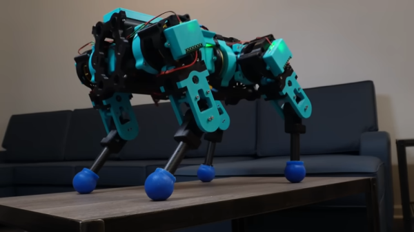
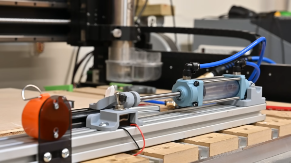
[Aaed Musa] has built a variety of robots over the years, but found off-the-shelf servos to be underwhelming for his work. Thus, he set out to build a better actuator to support his goals of building a high-performance walking bot in future.
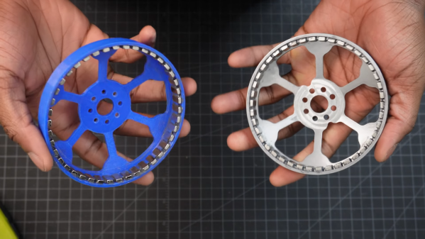
[Aaed] decided to try and build a quasi-direct drive actuator, similar to those used in MIT’s agile mini Cheetah robot. It consists of a powerful brushless DC motor driving a 9:1 planetary gear reduction built with 3D printed parts, which provides high torque output. It’s designed to be run with an ODrive S1 motor controller with encoder feedback for precise control.
The actuator weighs in at a total of 935 grams. It’s not cheap, with the bill of materials totaling just under $250. For your money, though, you get a responsive robotic actuator with a hefty holding torque of over 16 Nm, which [Aaed] demonstrates by having the actuator shake around some dumbells on a long lever arm.
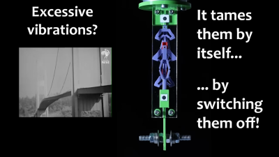
The key is a modified design based on the Kresling pattern, with each actuator having a specially-designed section (the colored triangles in the image above) that are designed to pop out under a certain amount of positive pressure, and remain stable after it has done so. This section holds its shape until a certain amount of negative pressure is applied, and the section pops back in.
Whether or not this section is popped out changes the actuator’s shape, therefore changing the way it deforms. This makes a simple actuator bi-stable and capable of different movements, using only a single pressure source. Stack up a bunch of these actuators, and with careful pressure control, complex movements become possible. See it in action in two short videos, embedded just below the page break.
We end up covering a lot of space topics here on Hackaday, not because we’re huge space nerds — spoiler alert: we are — but because when you’ve got an effectively unlimited budget and a remit to make something that cannot fail, awe-inspiring engineering is often the result. The mirror actuators on the James Webb Space Telescope are a perfect example of this extreme engineering, and to understand how they work a little better, [Zachary Tong] built a working model of these amazing machines.
The main mirror of the JWST is made of 18 separate hexagonal sections, the position of each which must be finely tuned to make a perfect reflector. Each mirror has seven actuators that move it through seven degrees of freedom — the usual six that a Stewart platform mechanism provides, plus the ability to deform the mirror’s curvature slightly. [Zach]’s model actuator is reverse-engineered from public information (PDF) made available by the mirror contractor, Ball Aerospace. While the OEM part is made from the usual space-rated alloys and materials, the model is 3D printed and powered by a cheap stepper motor.
That simplicity belies the ingenious mechanism revealed by the model. The actuators allow for both coarse and fine adjustments over a wide range of travel. A clever tumbler mechanism means that only one motor is needed for both fine and coarse adjustments, and a flexure mechanism is used to make the fine adjustments even finer — a step size of only 8 nanometers!
Hats off to [Zach] for digging into this for us, and for making all his files available in case you want to print your own. You may not be building a space observatory anytime soon, but there’s plenty about these mechanisms that can inform your designs.
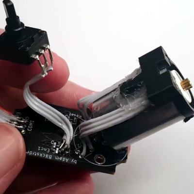
When [Scott Bezek] got his hands on a AS5600 magnet sensor breakout board, that’s just what he did. The sensor itself is an IC situated in the middle of the board, which in Scott’s design sits on a 3D-printed carrier. A bearing mount sits atop it, which holds — you guessed it — a bearing. Specifically a standard 608 skateboard bearing, which is snapped into the mount and held securely by a zip tie cinched around the mount’s tabs. The final part is a 3D-printed knob with a tiny magnet embedded within, perpendicular to the axis of rotation. The knob slides into the bearing and the AS5600 reads the orientation of the magnet.
Of course, if you just wanted a rotary knob you could have just purchased an encoder and been done with it, but this method has its advantages. Maybe you can’t fit a commercially-available encoder in your design. Maybe you need the super-smooth rotation provided by the bearing. Or maybe you’re actually building that robotic arm — custom magnetic encoders like this one are extremely common in actuator design, and while the more industrial versions (usually) have fewer zip ties, [Scott]’s design would fit right in.
Brushless motors can offer impressive torque-to-size ratios, and when combined with complex drive control and sensor feedback, exciting things become possible that expand the usual ideas of what motors can accomplish. For example, to use a DC motor in a robot leg, one might expect to need a gearbox, a motor driver, plus an encoder for position sensing. If smooth, organic motion is desired, some sort of compliant mechanical design would be involved as well. But motors like the IQ Vertiq 6806 offered by [IQ Motion Control] challenge those assumptions. By combining a high-torque brushless DC motor, advanced controller, and position sensing into an integrated device, things like improved drone performance and direct-drive robotic legs like those of the Mini Cheetah become possible.
IQ Vertiq 6806 brushless DC motor with integrated controller, driver, and position sensing.
First, the bad news: these are not cheap motors. The IQ Vertiq 6806 costs $399 USD each through the Crowd Supply pre-order ($1499 for four), but they aren’t overpriced for what they are. The cost compares favorably with other motors and controllers of the same class. A little further than halfway down the Crowd Supply page, [IQ Motion Control] makes a pretty good case for itself by comparing features with other solutions. Still, these are not likely to be anyone’s weekend impulse purchase.
So how do these smart motors work? They have two basic operating modes: Speed and Position, each of which requires different firmware, and which one to use depends on the intended application.
The “Speed” firmware is designed with driving propeller loads in mind, and works a lot like any other brushless DC motor with an ESC (electronic speed control) on something like a drone or other UAV. But while the unit can be given throttle or speed control signals like any other motor, it can also do things like accept commands in terms of thrust. In other words, an aircraft’s flight controller can communicate to motors directly in thrust units, instead of a speed control signal whose actual effect is subject to variances like motor voltage level.
The “Position” mode has the motor function like a servo with adjustable torque, which is perfect for direct drive applications like robotic legs. The position sensing also allows for a few neat tricks, like the ability to use the motors as inputs. Embedded below are two short videos showcasing both of these features, so check them out.
Even the oldest of mechanisms remain useful in modern technology. [Skyentific] has been messing with robotic joints for quite a while, and demonstrated an interesting way to use a pulley system in a robotic joint with quite a bit of mechanical advantage and zero backlash.
Inspired by the LIMS2-AMBIDEX robotic arm, the mechanism is effectively two counteracting sets of pulley, running of the same cable reel, with rollers allowing them to act around the bend of the joint. Increasing the mechanical advantage of the joint is simply a matter of adding pulleys and rollers. If this is difficult to envision, don’t work as [Skyentific] does an excellent job of explaining how the mechanism works using CAD models in the video below.
The mechanism is back drivable, which would allow it to be used for dynamic control using a motor with an encoder for position feedback. This could be a useful feature in walking robots that need to respond to dynamically changing terrain to stay upright, or in arms that need to push or pull without damaging anything. With properly tensioned cables, there is no backlash in the mechanism. Unfortunately cables can stretch over time, so it is something that needs to be considered when using this in a project.
Pulley systems have been with us for a very long time, and remain a very handy tool to have in your mechanical toolbox. A similar arrangement is used in the Da Vinci surgical robots to control their tiny manipulators. It would also be interesting to see this used in the already impressive robots of [James Bruton]. Continue reading “Cable Driven Robotic Joint”→
One of the challenges with humanoid robots, besides keeping them upright, is finding compact combinations of actuators and joint mechanisms that allow for good range of smooth motion while still having good strength. To achieve that researchers from the IRIM Lab at Korea University of Technology and Education developed the LIMS2-AMBIDEX robotic humanoid upper body that uses a combination of brushless motors, pulleys and some very interesting joint mechanisms. (Video, embedded below.)
The wrist mechanism. Anyone willing to tackle a 3D printed version?
From shoulder to fingers, each arm has seven degrees of freedom which allows the robot to achieve some spectacularly smooth and realistic upper body motion. Except for the wrist rotation actuator, all the actuators are housed in the shoulders, and motion is transferred to the required joint through an array of cables and pulleys. This keeps the arm light and its inertia low, allowing the arms to move rapidly without breaking anything or toppling the entire robot.
The wrist and elbow mechanisms are especially interesting. The wrist emulates rolling contact between two spheres with only revolute joints. It also allows a drive shaft to pass down the centre of the mechanism and transfer rotating motion from one end to the other. The elbow is a rolling double jointed affair that allows true 180 degrees of rotation.