When you hear about a switching power supply, you think of a system that uses an inductor and a switch to redistribute energy from the input to the output. But the original switching power supply was the vibrator supply, which was common in automotive applications back in the middle part of the last century. [Mr. Carlson] has a 1950s-era example of one of these, and he invites us to watch him repair it in the video below.
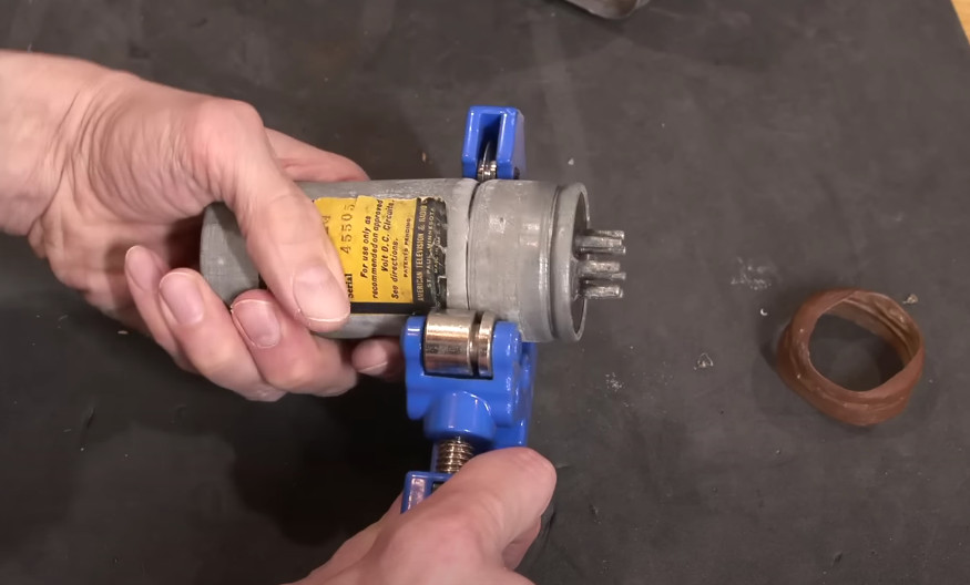
Most of the vibrator supplies we’ve seen have been built into car radios, but this one is in a box by itself. The theory is simple. A DC voltage enters the vibrator, which is essentially a relay that has a normally-closed contact in series with its coil. When current flows, the relay operates, breaking the contact. With no magnetic field, the springy contact returns to its original position, allowing the whole cycle to repeat.
You might wonder why you want to make and break a DC circuit in that way. Simple. With a little filtering, you get some sort of AC output, and AC is manageable with transformers, another magnetic device. In a radio, the resulting AC might return to DC to provide plate voltage for tubes. This unit has an AC outlet, although we imagine the voltage coming out would be hard to predict.
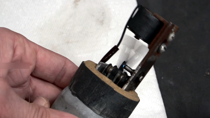
In this case, the voltage coming out was easy to guess: nothing. Guessing that the vibrator itself was shot, he tested the coil inside and found it was probably working. However, the unit would not oscillate. Given that it is a 70-year-old mechanical device, this isn’t totally surprising. The next step was to use a pipe cutter to open the can. Cleaning the contacts resulted in the buzzing noise that gave the device its name.
We’ve written before about vibrators and their high-powered twin, the dynamotor (or MG set, if you learned it that way). Many drug store tube testers could also test vibrators.


A vibrator is in no sense what we would today call a switching power supply. It is a simple transformer AC inverter, same as the class D transistor based one that used to charge camera flash capacitors.
The Wikipedia schematic ( https://en.wikipedia.org/wiki/File:HV_Vib.jpg ) seems like pretty basic unregulated isolated push-pull converter. Same topology with semiconductors is still used in many isolated applications for low-power use, because of the simplicity of skipping the feedback.
I see no reason not to call this SMPS.
WW2 radio sets had vibrators battery powered radios – so before the 1950s
Yes it is old tech. A lot of them also had MGs or dynamotors.
In battery powered portable radios? Why? B batteries were very common, and would be much more efficient than using a vibrator to boost a low voltage battery voltage up to plate voltages.
Radios powered from vehicle power supplies are a different story — these are the ones that would have a use for a vibrator supply.
Batteries weigh a LOT more than a vibrator. Weight was the biggest issue for field radios in WWII.
But a battery to supply high voltage will weigh a LOT less than a vibrator and the additional A battery size needed to provide that additional energy. That was the whole point of a B battery.
Mechanical DC to AC conversion was common prior to the 1950’s. The Ford Model T spark coil is a good example. It used a mechanical vibrator in series with a capacitor to produce AC that was stepped up by a transformer to produce a high voltage spark. Interestingly, it had a spark coil assembly for each of its spark plugs.
Back in the early ’80s, I had a 1950 pickup still sporting the original 6 volt electrical system. The only 6v radio I could lay my hands on for it used vacuum tubes. When you turned it on, you could hear the vibrator in the power supply buzzing, especially while waiting for the tubes to warm up (before any music/sound could play).
I remember those days, and the memories that come with it.
I had one of those as a kid (it was old when I got it : ) Also was found on old electric (battery) fencers and on one of those carbide cannons used to scare crows out of the corn (ignition spark). Also good for simple metal engravers etc. Around here they were called induction coils and were not inverters as they produced pulsating DC not AC.
When I was in my teenage years, I garbage picked almost the same unit from an alarm company. It was used as a battery back up in case the mains failed. Very cool to see another one.
I’ve had students build some of these by mistake: when trying to latch a relay in an electromagnetic circuit, wiring the latching feed through a normally-closed contact instead of a normally-open one. It makes a fair old unexpected racket!
I only know this concept from old-fashioned doorbells. Never occurred to me that you could use that as an inverter, that’s pretty neat.
Sad to say I remember these. That was how you got a tube radio to work in a car before semiconductors. The tubes were wire ended soldered in because otherwise the vibration would shake the out of their sockets.
I have one vibrator supply where the vibrator wouldn’t work even when trying the trick of AC on the coil. I gutted the can and put in a couple of IRF510s driven by a couple of 2N3904s configured as a multivibrator. RF noise wasn’t an issue even with the supply next to a BC-348 receiver. Maybe it’s the low 915 kHz intermediate frequency, but that receiver seems particularly susceptible to noisy switchers.
I knew a guy who worked on radio transmitters that had this kind of power supply. The buzz would change pitch with the load.
He said the easiest way to tune the antenna for maximum transmit power was to listen to the buzz. The best antenna match would cause the transmitter to pull maximum power. Adjust the antenna tuner and listen for a characteristic buzz from the power supply.
Haha switching power supply go brrrrrrrrrr
No … this is most definitely not what anyone who knows how a switching power supply works would call a switching power supply.
Then enlighten us exactly how it is not.
If you mean ‘not a switching power supply’ here is my take. A switcher takes rectified ac and pluse width modulates it into voltage regulated DC. This thing just changes DC to ac.
I’d hazard that there are more dc-dc switching power supplies deployed than ac-dc ones, actually. Most buck or boost converter topologies are technically switching power supplies.
They even had synchronous vibrators, more pins same can. The second set of contacts switched the transformed B+to DC sans rectifier. Neat! Only playing the radio for a song before worrying about the battery with the engine off, not.
Yup. ’57 Chevy radio. First you heard the vibrator, then the tubes warmed up and it came on.
Sometimes it took a good fist slam to get the vibrator going. Good times!
I think that may be my atr50 I recently sold on ebay!
How did this not generate so much interference that the AM radio it was powering would have been useless? The metal can, plus capacitors?