A LiIon pack might just be exactly what you need for powering a device of yours. Whether it’s a laptop, or a robot, or a custom e-scooter, a CPAP machine, there’s likely a LiIon cell configuration that would work perfectly for your needs. Last time, we talked quite a bit about the parameters you should know about when working with existing LiIon packs or building a new one – configurations, voltage notations, capacity and internal resistance, and things to watch out for if you’re just itching to put some cells together.
Now, you might be at the edge your seat, wondering what kind of configuration do you need? What target voltage would be best for your task? What’s the physical arrangement of the pack that you can afford? What are the safety considerations? And, given those, what kind of electronics do you need?
Picking The Pack Configuration
Pack configurations are well described by XsYp:X serial stages, each stage having Y cells in parallel. It’s important that every stage is the same as all the others in as many parameters as possible – unbalanced stages will bring you trouble.
 To get the pack’s nominal voltage, you multiply X (number of stages) by 3.7 V, because this is where your pack will spend most of its time. For example, a 3s pack will have 11.1 V nominal voltage. Check your cell’s datasheet – it tends to have all sorts of nice graphs, so you can calculate the nominal voltage more exactly for the kind of current you’d expect to draw. For instance, the specific cells I use in a device of mine, will spend most of their time at 3.5 V, so I need to adjust my voltage expectations to 10.5 V accordingly if I’m to stack a few of them together.
Now, where do you want to fit your pack? This will determine the voltage. If you want to quickly power a device that expects 12 V, the 10.5 V to 11.1 V of a 3s config should work wonders. If your device detects undervoltage at 10.5V, however, you might want to consider adding one more stage.
How much current do you want to draw? For the cells you are using, open their spec sheet yet again, take the max current draw per cell, derate it by like 50%, and see how many cells you need to add to match your current draw. Then, add parallel cells as needed to get the capacity you desire and fit the physical footprint you’re aiming for.
The last word for section this is on safety. When working with packs that exceed 20V , you are at a higher risk of injury than with the usual low-voltage electronics. DC doesn’t shock you the way AC does, it makes your muscles contract in a way that risks you holding onto whatever is shocking you, and, it also can fry your muscles from the inside. If you’re working with ebike packs, you should seriously heed the advice of having one hand in your pocket as much as humanly possible.
Not only that, but working with LiIon packs is physically dangerous even if you don’t get shocked. At a certain pack voltage and capacity, a short-circuit can blind you, and it will easily melt your metal tools – use plastic as much as possible. If it can drive your ebike motor, it contains enough energy to do a lot of damage.
Thankfully, in the end, safety is manageable. Plus, there’s electronics that help you take care of it.
Electronics And Balancing
In terms of circuitry, you need three things for a LiIon pack – charging, protection, and balancing. So, let’s start with balancing, because balancing circuits give you some much-needed insights into LiIon pack charging requirements.
Balancing is seriously required for LiIon packs that have more than one cell in series. A LiIon charger chip by definition doesn’t monitor individual stages in the series. Over time, the stages in any pack will develop mismatches in internal resistance and capacity, if they’re not noticeably present by the moment the pack is built. During charging, this means that some of the stages might get fully charged while other stages haven’t finished charging yet – and a LiIon charger that’s only connected to the single series ground and output can’t detect that, so it will continue pumping current into the pack, which might lead to overcharging.
 Balancers are circuits you build into the LiIon pack directly, in parallel with every stage, that contain a hefty resistor and can shunt the entire charging current away from a cell stage when the voltage on the stage exceeds the maximum voltage threshold. As the pack is charging, the balancers will turn on one by one, protecting the stages with lowest capacity from overcharge. Balancers are simple: you can build one with a resistor, TL431, and a random FET from a desktop motherboard. Of course, there is a balancer available on the market for nearly every battery configuration too.
You have to add a balancer if you want your pack to be safe, doubly so with high stage count packs where even miniscule differences will soon be exacerbated. And triply so if you’re making your pack out of salvaged batteries, which may have mismatches that series charging would exacerbate.
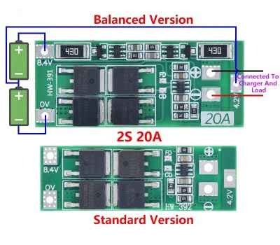
If you’re looking for a protection circuit that does balancing for you, look out for rows of SMD resistors on the board. Balancers are not a substitute for a badly built pack – they can’t dissipate all that much current; ultimately, they are safeguards that help keep a good pack from going bad, and you need them just as much as you need both the charging and protection circuits.
Charging And Protection
Once you move to a multi-stage pack, the classic TP4056 single-stage chargers will not work anymore, as much as I love them. Instead, get a charger chip that can handle series configurations – you can find them reasonably easily. For low-count-series and high-count-series packs, there are plenty of charging circuits on Aliexpress. For low-count-series packs, these circuits take the form of small modules, TP4056-like, just explicitly being marked “2s” or “8.4 V”. 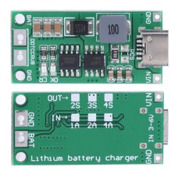
Best is if everything is under your control. You must have control over charger’s configured termination voltage, or at least know what voltage it’s set to – too high and you overcharge, which is pretty bad; too low and you undercharge, which is actually beneficial for pack health but will result in you losing out on capacity. You will likely want control over charging current, too – just like with voltage, it can be too small, but it can’t be too large.
As with the single-cell setups, there are also multi-series protection circuits that safeguard you from overcurrent and overdischarge. These aren’t meant as a substitute for proper handling, but they can protect you from accidents like short-circuits on the output or a charger going haywire; not that there can’t be a spark, but the spark’s consequences will be greatly diminished.
It’s even more convenient when the balancing circuit and overdischarge are included in one PCB. These battery management system boards (BMS) are plentiful on the market and take care of everything under one roof. Look for large SMD resistors as a good indicator that the circuit has balancing as well as overcurrent protection. These boards often lack programmable overcurrent thresholds, though, so be ready to find part numbers for extra FETs and solder them onto conveniently unpopulated footprints if you want to up the limit.
These are the basics you need to work with a multi-stage pack. Is anything unclear? Ask in the comments below – this is the kind of topic where misunderstandings are worth getting corrected early.


>DC doesn’t shock you the way AC does, it makes your muscles contract in a way that risks you holding onto whatever is shocking you, and, it also can fry your muscles from the inside.
DC actually paralyzes the muscles by polarizing the ion channels in the nerves and not letting them recover for as long as the current flows, which stops the nerve impulses going. You find you can’t pull your hand away, because your arm goes entirely limp and won’t follow your command.
The misconception that DC is more dangerous and causes you to latch to stuff comes from alternator/magneto powered DC systems which actually have a strong and relatively high frequency ripple on them. It’s the AC ripple that’s making you grab on to the wiring to the point that you can’t yank yourself off.
DC doesn’t inherently “fry your muscles on the inside”. AC does the same thing, since at low 50/60 Hz frequencies it passes through almost equally well. The risk is that since you don’t necessarily notice you’re passing significant amounts of current, since it isn’t tickling your nerves like AC does, the first sign of trouble may be the sudden smell of bacon. However, that isn’t going to be a big concern until you go past a hundred Volts or so.
https://www.ncbi.nlm.nih.gov/pmc/articles/PMC2763825/
“Nearly all cases of inability to let go involve alternating current. Alternating current repetitively stimulates nerves and muscles, resulting in a tetanic (sustained) contraction that lasts as long as the contact is continued. (…) In contrast, with direct current, there is only a feeling of shock when the circuit is made or broken. While the contact is maintained, there is no sensation of shock. Below 300 mA DC rms, there is no let-go phenomenon because the hand is not involuntarily clamped. There is a feeling of warmth while the current travels through the arm. Making or breaking the circuit leads to painful unpleasant shocks. Above 300 mA, letting go may be impossible.”
Note: human body resistance goes down to about 300 Ohms with a relatively large contact area if you’re soaked in salt water (e.g. sweaty palms). Getting past 300 mA requires over 90 Volts DC across both hands in the worst case scenario.
For a bit of sadistic detail, see Figure 5 where they describe a setup where a person is standing in two buckets of water and being electrocuted:
“Initial testing has shown that with 3.05 V (60-Hz AC rms) applied between the plates, a current of 8.65 mA flowed, resulting in involuntary flexion of the knee to 90°. This flexion could not be overcome with voluntary effort.”
It takes surprisingly small AC voltages and currents to completely mess you up if you’re unlucky or very stupid. That’s the reason why the ripple voltages in the DC systems of old tripped so many people – and lead them to think that the DC is causing it. They might have been e.g. adjusting the timing of a brushed DC motor live as it runs, without realizing that the sparks in the brushes are making strong AC.
Mention center tapped packs and external balancing chargers?
Also mention fire proof charging bags. Not just for HobbyKing grade battery packs anymore. You have no idea where that Alibaba/Amazon cell has been.
Design your device assuming the battery will go into thermal runaway. Remote batteries on winter testicle warmer.
1.5 V can kill you. If you get it through the skin and current goes through your brain. A small open wound can change everything, so can being wet. Don’t hack up a home electroshock machine, no matter how crazy you might be. Beware any electrodes attached to head, instrument amplifiers with current limited power supplies. You can’t stimulate the pleasure center of the brain without surgery. Don’t try. I digress.
I should say, ‘You can’t electrically stimulate the pleasure center of the brain without surgery.’
Carry on ‘reading’ HackaDay. If that’s what ur into.
I’m still intrigued by this testicle warmer of which you speak
Quite a useful write-up that has the basics covered in one. One that would come in handy for many people, especially in higher power electronics like solar and Personal EVs.
The only thing I’m struggling to find is a guide on how to get results for high-side switched BMS.
I try searching for terms as the high side BMS and other terms like including “P-channel” as such.
The best I found was purely by chance of the picture where I can see the P+ terminating at the MOSFETs but the max I can find is at 10A rated load ._.
For the curious, the reason I’m looking for such a BMS for at least 20A is the battery pack I’ve built that I use to charge at work as “Perks of the job” (Boss knows, but doesn’t know how much energy I use to charge it, compensates the “minimum legal wage” I’m on).
The charger uses high-side current detection, whilst the “BMS” uses low-side switching of an external “Drill Stop” MOSFET, as does many BMS modules switch on the “low-side” of the load.
This means when I attempt to put in a common “safety ground”, the P- point means the charger is safer if it shorts a winding, but then if I connect a laptop and have an audio cable to a grounded amplifier, then when the battery voltage goes below cut-off the P- MOSFET would be bypassed through an audio cable at up to 12A (according to the DELL PSU at19V).
I toyed with other ideas with equal risks of bypassing something important due to negative switched loads and grounding, like if I put the Safety Ground at the MOSFET output B-, then the switched off MOSFET means I get a tingle from the Class-Y capacitor and a risk of shock if something burns up.
P.s. Lesson learnt, but no solution.
Ah, instead of stealing pens, paper and other office supplies you take home some electrically charged chemicals? ;-)
Batteries are often found in the Office Supply cabinet.
I’m using a MAX1614 and high power N ch FET for high side switching and “last resort” hardware auto cutoff (6.4v target on 2S1P RC pack), then per-cell ADC (per-cell divider connected to balance plug is FET-switched off, so is MAX1614 voltage divider, when powered off) for code-side voltage monitoring under high load (a bit over 20A max). Charging is offline, via RC balance charger.
I’ve not found a decent single-chip solution for high amp draw 2S1P with per-cell monitoring, soft on / off single switch or embedded off, and hardware auto cutoff, this is the closest solution I’ve found, coupled with a small pile of discrete parts. Voltage-divider-off may be excessive, but it’s worth $2 to me. No thermal monitoring for discharge or any in-circuit charging, though. I’d rather charge externally, “just in case” sketchy RC pack does a bad thing.
If someone has a better (workable) suggestion, would love to hear it!
Can you draw a diagram in falstaff simulator and pass a link? There might be some ideal diode controllers with separate on/off logic that could be pressed to service here by detecting a low-side switch off event and simultaneously cut off the high side to the load.
For this specific situation you described, there’s an easy workaround: use Bluetooth audio. Or if you require higher quality than Bluetooth, use an optical SPDIF cable.
Anyways, I don’t think you really need to ground the battery. Ground everything after the BMS and leave the negative of the battery floating.
Also, if you’re on minimum wage, there should be no shame to take as much as you can from everything at work.
I couldn’t find it – the great HaD search button – but a while ago there was an article about someone doing batteries for their electric car who had tied them all together with relay controls, ie he could switch both the charger from cell to cell, and pick batteries out of the pool to discharge.
I keep wondering why that approach is not used more often ie charge each cell individually, and drop poor cells out of the discharge…
The concept is pretty simple. To be able to individually charge or bypass a cell, you need a switching element on both ends of the cell. An EV battery is normally 100 cells in series or more. Even assuming we build switching elements which serve to block bi-directionally (This gets difficult with semiconductors) we are still talking 100 devices in series. Even if each is only 50mOhm, 100 in series is 5 ohms. That is a lot of lost power that must be dissipated as heat, even worse the series impedance reduces the range of the vehicle.
This is only half the problem. Next we have the issue of building a huge mux, capable of very high voltage differentials within the mux, where the midpoint of the mux nodes can be lower or higher than other inputs of outputs of the mux. This is a big interconnection issue, not to mention the cost and weight of the switching devices, in addition to their increased resistance and cost.
When working in this area, I had people show up at my desk monthly, telling me that had a groundbreaking idea for a patent. They envisioned this huge mux capable of bypassing any cell, shuttling charge between cells, discharging some while charging others. It is a great idea, until you look at what it takes to do this, and the impedances introduced and the cost implications. After challenging them to show me a real world way of achieving this, they would come back days or weeks later, either saying they were unsuccessful, or showing their solution that failed to account for some real world phenomenon. This is a tough problem to do in an elegant way. It gets brute force, big, ugly and costly in a hurry!
try this:
https://www.google.nl/search?q=site%3Ahackaday.com+electric+car+relay+controls
I took apart a laptop battery and wrapped around the 3s 2p pack was narrow green plastic tape with Chinese letters and FRESH, normally used to gently wrap asparagus and such! Build your packs carefully.
Charge termination is based on a current and voltage value. Temperature is also important. Most ‘lithium charger’ modules (basic CV/CC DC/DC converters) do not include this critical feature.
It’s safer to use a JEITA compliant charger IC.
“It’s even more convenient when the balancing circuit and overdischarge are included in one PCB”
I argue that this is even more vital than balancing. This should be the minimum standard for any DIYer working with multi-cell Li-Ion packs.
Why? because if your balancer fails, or simply can’t keep up with cell self discharge, it’s the protection circuit that prevents an overcharge triggered battery fire.
I feel like in the next article it could be useful to tell us more in depth about lithium batteries. Like what happens to them if they go below a certain voltage threshold, how risky is it to recover undervolted cells, how to recover them (charge with tens of mA until they’re up to 3 volts again), how to test them for damage, how to arrange and match cells when forming a pack (for instance, there are websites where you input your cell data and they tell you how to group your cells to make sure every parallel array has similar capacity), electron microscope images of the dendrites forming in the electrodes, instructions to test cells internal resistance and current capacity accurately, what type of cells can be safely used for drill packs and how to build that pack with safety features such as a reverse polarized diode to absorb voltage spikes, explanation of the most common failure modes, charts showing temperatures impact the cell’s lifespan and capacity to provide current, reasons why cell capacity fluctuates along its lifetime, a review of smart BMS such as JBD, ideas how to build a case that would contain the flames (is a fine metal mesh enough to vent the hot gas while containing the flame?) if a battery pack goes into thermal runaway, or how to accommodate batteries during charging to make sure that risks are mitigated – for instance, I charge my scooter in the bathroom where ceramic tiles aren’t likely to catch fire, and I charge individual cells leaving the charger on a ceramic plate. Also some word of advice with real life examples, such as: a cell (specially if it has been undervolted) may look like it’s charging normally, but then it will not be able to reach full voltage (why does this happen?) and the CC/CV charger will keep pushing charge into the cell, making it go extremely hot and potentially explode.