Most of the Hackaday community would never wire a power supply to a circuit without knowing the expected voltage and the required current. But our mechanical design is often more bodged. We meet folks who carefully budget power to their microcontroller, sensors, and so on, but never measure the forces involved in their mechanical designs. Then they’re surprised when the motor they chose isn’t big enough for the weight of their robot.
An obstacle to being more numbers oriented is lack of basic data about the system. So, here are some simple tools for measuring dynamic properties of small mechanisms; distances, forces, velocities, accelerations, torques, and other things you haven’t thought about since college physics. If you don’t have these in your toolkit, how do you measure?
Distance
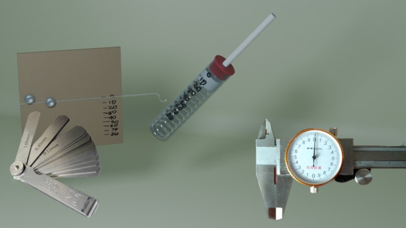
For longer distances the usual homeowner’s tools work fine. The mechatronics tinkerer benefits from two tools on the small end. A dial or electronic caliper for measuring small things, and a thickness gauge (or leaf gauge) for measuring small slots.


A thickness gauge is just metal leaves in different thicknesses, bolted together at one end. Find a combination of leaves that just fits in the space.
Force
Here’s four force measuring tools we use to cover different magnitudes of force: a postage scale, a push stick, a spring scale, and a letter scale. The postage scale is best purchased. For big things, the bathroom scale works.
A push stick is a force measurement device that you can make yourself. We first saw one of these used to tune slot cars, but they’re universally useful. It’s a simple pen shaped device made with a barrel from any small transparent parts tube, a spring, and a plunger with a protruding pin. Grasp the barrel and push the gizmo with the pin, and you can read the force off the tube.
If you need it to be calibrated, remember that you just bought a postage scale. Push it into the scale and mark off reasonable increments. Make several, in different sizes. A Z or L shaped plunger is useful for hard to reach places.

The conventional spring tension scale is useful, but most commercial ones are terribly made and inaccurate. You can make yourself a better one. They are useful for measuring the spring constant of springs, for learning the tractive effort needed to move a robot, finding the center of gravity of a robot arm, and a hundred other ‘how much oomph’ things. Again, it’s just a matter of connecting a hook to a spring, and measuring its deflection.
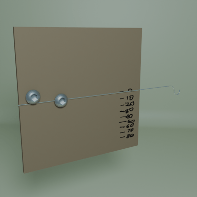
For yet lighter weights, you could buy a letter scale, at least in the old days. Today you might have to make your own. It can be as simple as a piece of spring steel fixed to a sheet of calibrated cardboard.
Torque
Torque measurements are good not only for sizing actuators, but for measuring efficiency.
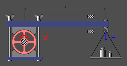
How you do torque measurements depend on the speed you want to make them at. For static loads, just put a lever of known length on the shaft and measure the force. Torque = distance * force. For fast rotating systems, you can run the system at a known speed and measure the electrical energy used.
If you just want to apply a varying known torque to measure efficiency, your life is much easier. Mount a broad wheel of some sort on the shaft — RC airplane tires work well. Drape a piece of ribbon over the tire. Anchor it at the “out” end and hang a small weight at the “in” end. This is a Prony Brake, and it’s a useful device to know about. The force on the outside of the wheel is just enough to lift the weight – after that the ribbon slips. The measured torque is then the weight times the wheel radius.
You may also want to measure speeds and accelerations. Here, the ubiquity of cell phone cameras is your friend. Suppose you’re animating a crane on your model railroad. Record yourself on video moving the crane with your hands against a protractor to get a feel for speed and acceleration. In video editing software check the positions for various frames, and you now have position changes. The number of frames and distance can help you calculate the speed, and the change in speed vs time is acceleration.
If your mechanism is moving too fast for video, use a fast phototransistor or hall effect device and an oscilloscope, or gear down by holding a toy wheel against the shaft and measure the more slowly rotating wheel.
In the crane example, the torque you need to supply is the frictional torque plus the acceleration torque, and to calculate the acceleration torque you need the moment of inertia. For refresher: angular acceleration = torque / moment of inertia (ω = τ / I) and moment of inertia = mass * radius2 (I = m * r2 ) for point mass.
You can drive the crane with a repeatable torque, say using a pulley and weight or a motor, and get the acceleration ω1 from the still frames on your video. If you repeat this with a known mass m a known distance r from the shaft axis, like a lump of putty on the end of the crane arm, you can get a second value: ω2.
Write the ω = τ / I equations, ω1 = τ / Icrane and ω2 = τ / (Icrane + r 2 * m). Combining and isolating Icrane and holding our tongues just right, Icrane = r2 * m / (ω1 / ω2 – 1).
Be careful to subtract the moment of inertia of your measuring apparatus, and add in the moment of inertia of the final drive if needed. Now you can size your servo with some confidence. Believe me, once you’ve done this a couple times, you’ll never go back to winging it.
Power
The easiest way to get a ballpark feel for power is to simply measure the system’s consumed power by measuring the electrical power at the motor, but this ignores losses in the drive train. And losses are one of the really interesting things to measure. Bad performance is usually friction, and efficiency is a goal for other reasons than just motor sizing or battery life. It’s a measure of how janky your setup is.
Does your model train or robot run poorly? Set it to climb a steep grade on a test track. Calculate the work it does: mass * height change. Measure the input electrical power and the time, Energy = V*I*T. You now have an idea of how much the actual power consumption differs from the maximally efficient system. Any power that went in but didn’t appear as potential energy in the choo-choo’s new position is frictional loss. Now you can experiment with loosening and tightening screws, changing gear mesh, and such, and have some idea if you’re making things better or worse.
Conclusion
None of the above was rocket science, and you don’t need to do some complex FEM analysis to make the average hacker project. But a bit of real engineering can go a long way towards more reliable mechanisms, and that starts with knowing the numbers you’re dealing with. Taking the required measurements can be simple if you know how to build the tools you need, and your life will be easier with some numbers to guide you.


So guilty of this ☺️
I tend to go with ehat “looks sufficiently beefy”.
*what
90% of mechanical engineering is this. You don’t simulate a lot of things, you don’t calculate a lot of things. You guess how strong it might needs to be, do it times 5. And off to the next thing.
Why calculate if an M4 bolt might be strong enough if you know M8 will be, and you build the whole machine with just M8 bolts will make assembly and service way more happy then using various sizes all over the place.
Space constraints, mass and cost are three very valid reasons to calculate if the bolts used are strong enough.
I don’t know where you work as a mechanical engineer if most of your work is just guessing what’s good enough, but I certainly wouldn’t want to work there or use any products from there.
Legal reasons are also a very valid reason to calculate, simulate and test everything. If your product fails and someone gets injured because of a broken bolt and your answer is just that you guessed the bolt would be strong enough then I don’t think that would go down well.
Why design when you can overbuild?
Then the real engineers come in and mandate M4 bolts, then the “value engineers” follow behind and advocate M3 bolts, but only half the number. And the cheapest grade. And no washers.
Though washers are almost always unnecessary. They’re only used if you’re bolting down very thing stuff, or very soft stuff.
Very thin stuff – curse you auto-complete.
So, for example, you want to build a small audio amplifier. You calculate the resistor values for the dividers, but you do not calculate the exact power dissipation for each, you just pick “big enough”. You don’t calculate the minimum thickness and width for every pcb trace, you do not calculate the forces on the housing, you just pick one. You do not calculate the torque for the screws in that housing, nor that for the mounting screws holding the pcb. The bypass capacitors are not exactly the necessary size in voltage and capacity, but just the standard filter caps you always use.
Tl;dr: I wouldn’t want to work at or use any products from a place where the engineers are required to calculate all that just to squeeze out any safety margins while producing a product with highly specialized components where you could just use what is common.
Besides: didn’t you miss anything when defining the forces each screw, each knob and each plug has to withstand before starting the calculations?
Then you outsource manufacturing to China and the subcontractors use the cheapest components they can find or whatever they have on hand.
Every product has critical and non-critical features. If you optimize a non-critical feature that costs a small fraction of the total, you’re wasting effort and losing the company money for being pedantic.
Masking tape and/or a bigger hammer usually suffices…
A phrase I frequently heard (and used) growing up in Down East Maine – “Well, that oughta hold er”
I remember buying a replacement toilet seat at local Leroy Merlin. Turns out it didn’t fit my bowl. Another trip to LM to buy some masonry drills to make new holes. While drilling the entire bowl shattered .__.”
Only then I learned that ceramics should be drilled with a special, very sharp drill bits and not general-purpose masonry ones.
In my hardware store, a toilet seat is cheaper than even a normal masonry drill. But I never knew toilets came with nonstandard hole sizes!
IIRC, in the USA, only 2 different spacing of holes for toilet seats are allowed.
But you have to flush 15 times, and there’s no water coming out of the shower!
In the spirit of this – I printed a fixed-value torque wrench for changing 3D printer nozzles. To calibrate it, I printed an arm that fit onto the output, and then placed it on a scale while turning the wrench, until it slipped. Since the arm was a known length, I calculated the slip torque, and it was close enough to what I needed.
Link?
If I understand the part with the Prony Brake correctly, you measure too much torque this way, because you assume the force on the “out” end is zero. Instead use a spring on this end, and mark the zero torque position and the unknown torque position. The spring constant times the difference between those two is the force you want to know for torque calculation. You get the spring constant by measuring the forementioned positions with zero torque but different weights (one of which may be zero as well, but beware strange behaviour around the zero point in this case).
Thanks for ideas about force measurement with a spring and a metal rod. I will use these.
One of the most useful articles in a long time! Thank you very much!
Jeremy Fielding had a good video on measuring the torque output of small and medium motors, I imagine the technique could be applied in reverse too to measure torque required to move something.
An interesting tidbit I picked up from a motor designer is that Torque is roughly proportional to the rotor volume of the motor. This made sense after some thinking. The torque is produced by a sheer force in the gap between rotor and stator. That force will be proportional to the area of that gap – the surface area of the cylinder. The torque will be that force multiplied by the radius of the cylinder, and the result is a formula that is proportional to the volume. It also depends on other details like flux density and such, but with all other things equal it’s volume.
What is the difference between a letter scale and a postage scale?
The difference is just the scale (pun very much intended). Ballpark figures but in general:
Letter: precision = grams, max weight = hundreds of grams.
Postage scale: precision = a few grams, max weight = thousands of grams.
To extend the “scale” haha either way, you’ve got luggage, drug dealers/jewelers scales, and drug user/fine artists’ scales.
Luggage: precision = tens of grams, max weight = tens of thousands of grams.
Drug dealers’/jewelers’: precision = tenths/hundredths of a gram, max weight = tens of grams.
Artists/druggies’: precision = millgrams, max weight = a couple dozen grams.
When you get to milligram scales, especially cheap ones you have to be very specific and intentional with your usage, often the initial value shown is correct and then they’ll start to immeditately drift. They also don’t read incremental additions well, so you have to lift the weightboat for every adjustment of amount. Also the breeze from breathing or moving can read tens of mg.
They are however extremely useful when weightweenieing tiny parts, measuring tiny fluid amounts, measuring moisture content of an item, or getting consistent results while adding pigments to resins!
Weighing pills.
For small parts you want “counting scales”, you calibrate them by weighing a known amount, eg 100 screws, after that they’ll tell you how many parts you have.
Don’t forget the coffee scale 😉
Down to parts of a gram
Modern tech has provided us with digital scales** that are literally a hundred times less expensive and an order of magnitude smaller than the ones I used in college. Today I measure epoxy by mass rather than volume; it’s just as fast, and 3.14 times more accurate. ;-)
But if Soviet Roosha decides to EMP the US, whatchoo gonna do? Them digital scales ain’t gonna be nothin more’n paperweights! ;-)
“700 Science Experiments for Everyone”*** occupied a fair portion of my geek-ified youth. It showed several types of scales and balances that could be made at home. A balance, sensitive to a few milligrams, was constructed from a cork, a couple of pins, wire from a coat hanger, and bits of glass.
———-
**Scale: measures force. Balance: measures mass (as long as there’s some gravity lurking about).
***Readily and inexpensively available on auction sites. Get the old edition, printed in the early 1960s. Later printings deleted some of the more-interesting experiments, such as a version of the ammonium dichromate volcano that includes magnesium(!!!)
And for measuring small masses, you might need to consider the buoyancy of the atmosphere.
https://i.imgur.com/4u4TMX8.png
I remember an article from when I was a kid about making a scale using a center-zero microammeter. The meter would be set on its side, and the pointer twisted so you could sit an object on it. The weight was determined by the current required to move the pointer back to center. A pot in series with a battery provided the current, and knob position indicated the mass being weighed. Calibration was the tricky part… I think they used it to weigh ants as a demo of the sensitivity.
Another way to measure pull forces, such as how much force does it take to close this door, is to take some string and a water bottle. Tie string to bottle and door, use something smooth like a screwdriver to translate horizontal to vertical, and fill the bottle with water or rocks until you have a movement you are happy with. Weigh your bottle, and now you know! Multiply by 2-5 and that’s the size of motor you are looking for, to account for increased friction from environmental changes, plus also not running your motor at max all the time.
+1 for not designing to run at max. Especially if you want a control loop to control speed or position.
A thing I learnt far too late in life is that digital calipers can become less “true” as the battery voltage drops below a certain point (I don’t remember what). Do yourself a favour and make sure it either tells you when it’s going flat, and stop using it at that point; or get a mechanical one.