[Carl Bugeja] finds the engineering behind the Las Vegas Sphere fascinating, and made a video all about the experience of designing and building a micro-sized desktop version. [Carl]’s version is about the size of a baseball and crams nearly a thousand RGB pixels across the surface.
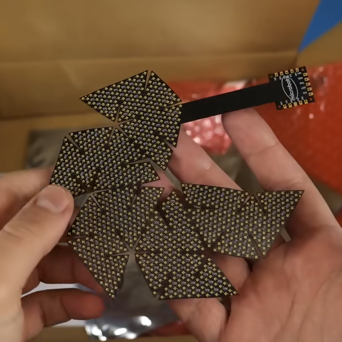
Putting that many addressable LEDs — even tiny 1 mm x 1 mm ones — across a rounded surface isn’t exactly trivial. [Carl]’s favored approach ended up relying on a flexible four-layer PCB and using clever design and math to lay out an unusual panel shape which covers a small 3D printed geodesic dome.
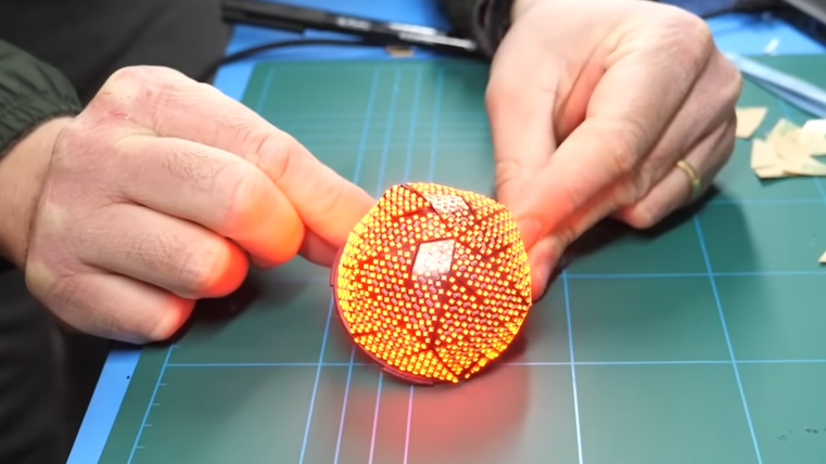
Much easier said that done, by the way. All kinds of things can and do go wrong, from an un-fixable short in the first version to adhesive and durability issues in later prototypes. In the end, however, it’s a success. Powered over USB-C, his mini “sphere” can display a variety of patterns and reactive emojis.
As elegant and impressive as the engineering is in this dense little display, [Carl] has some mixed feelings about the results. 945 individual pixels on such a small object is a lot, but it also ends up being fairly low-resolution in the end. It isn’t very good at displaying sharp lines or borders, so any familiar shapes (like circles or eyes) come out kind of ragged. It’s also expensive. The tiny LEDs may be only about 5 cents each, but when one needs nearly a thousand of them for one prototype that adds up quickly. The whole bill of materials comes out to roughly $250 USD after adding up the components, PCB, controller, and mechanical parts. It’s certainly a wildly different build than its distant cousin, the RGB cube.
Still, it’s an awfully slick little build. [Carl] doubts there’s much value in pursuing the idea further, but there are plenty of great images and clips from the build. Check out the video, embedded below.


Very interesting project! Due to the size constraints I wonder whether plastic fibres optics coupled to a flat array of LEDs might be a better option for the illumination? Maybe with 3D printed holder for the fibre array so the positioning of fibres can be held in place.
That might be good for nacelle caps of TOS USS Enterprise models—call Round2
That is a very clever idea! You could even go further, and use some kind of display instead of individual LEDs.
However, a problem is that the LEDs would be even closer than they are now, and making the light guides may not be so simple.
Use a round LCD at the base, with a bunch of fiber optic light guides bundled tightly (even glued?) together, then *somehow* turned into a hemisphere at the top? Not sure what options exist for machining fiber optics without destroying them in the process. Then you’d be limited in resolution by the number of fiber optics you can bundle together, as I doubt you’d exceed the resolution of the screen itself.
I imagine you could use a repeated dipping process similar to candlemaking, thickening the individual fibers into tapering conical shapes that you later fuse together and lathe into a sphere.
I think productionwise you could do better with normal PCB’s in triangular sections, densely packed with LED’s on the top side and the capacitors on the lower layer, that plug into a power and data source in a 3dprinted base, which would also make faults easier to rework.
But a very cool idea nonetheless!
This may also give space for shift registers, allowing the use of (cheaper) simple RGB LEDs, like a hub75 display.
or independent flex panels for their extreme thinness. keep the shift registers on the back side, along with a ‘vertical’ connector for spi going back to the central driver mcu. keeping them one big series chain is a difficult constraint to work around that doesn’t gain anything other than maybe easier fabbing. bonus: if you have a failed panel you can just sub it for any other panel.
To scale up; how about using a tiny video projector to project on the inside of the sphere? Although that probably does not produce enough light…
A MEMs raster scan laser projector could theoretically do the job quite well, since they don’t have to be focused and therefore could resolve pretty clearly across a sphere. The issue is they’ve all been out of production for years by now, r&d into them was seemingly abandoned.
I do have one, but I’d have no idea where to begin for software to distort the images for curved surface.
Go to trekbbs.com
They may be of help.
This would be a great warp nacelle dome.
I have heard it said the Gene Roddenberry wanted the later aft nacelle dome (and the “trench” in the sides of the nacelles) to have the same pattern corresponding/matching each other—as if a lightning globe ran the length of the tube.
I was wondering that too. I was at the Billy Graham Museum in Charlotte NC and in the middle of one room there was a sphere that had some kind of projector on the inside. You could walk around the sphere and see the same distortionless projection from all sides. The tour group moved on but I stayed because I wanted to see how it worked and if I could replicate it. Every time I see a globe I at a thrift shop I think on how it could be used to do this.
Sounds like a Pufferfish display (https://www.pufferfishdisplays.com/)
I didn’t realise they were still going – I saw them at the PLASA trade show probably 20 years ago.
To make the resolution seem higher, give it an orientation sensor, give it a spin, and rely on persistence of vision.
Oh, you have to try to make this design mass manufacturable. You could sell a lot of these things.
This bro became Victor and stole the sphere. LMAO
You have a nice product here!
I wonder if a non-white grey diffusor would work better.
And I wonder if you could use a solder mask to change the visual characteristics, are there metalic ones available yet? Reflective in some way I mean to suggest.
It might be a interesting differentiator for PCB makers to offer such if they don’t yet do so.
I mean they use white often for LED PCB’s, but if they could get in a pseudo-chrome variant that might be interesting to people/manufacturers.
I think you can do metalic-like effects without using metals right? But even if it had to use metals it would still be OK for LED PCB’s as long as the metals are contained in a non-conductive carrier.