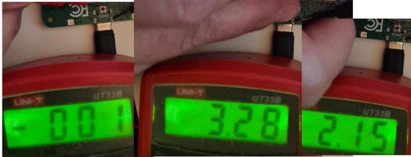
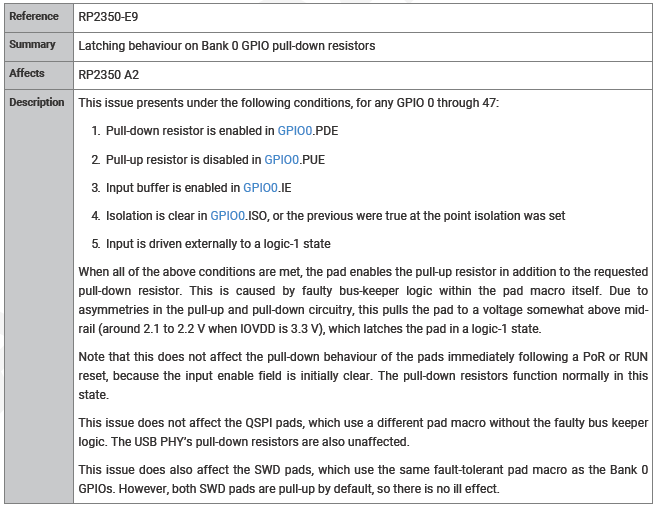
The newly released RP2350 microcontroller has a confirmed new bug in the current A2 stepping, affecting GPIO pull-down behavior. Listed in the Raspberry Pi RP2350 datasheet (page 1340) as erratum RP2350-E9, it involves a situation where a GPIO pin is configured as a pull-down with input buffer enabled. After this pin is then driven to Vdd (e.g. 3.3V) and then disconnected, it will stay at around 2.1 – 2.2 V for a Vdd of 3.3V. This issue was discovered by [Ian Lesnet] of [Dangerous Prototypes] while working on an early hardware design using this MCU.
The suggested workaround by Raspberry Pi is to enable the input buffer before a read, and disable it again immediately afterwards. Naturally, this is far from ideal workaround, and the solution that [Ian] picked was to add external pull-down resistors. Although this negates the benefits of internal pull-down resistors, it does fix the issue, albeit with a slightly increased board size and BOM part count.
As for the cause of the issue, Raspberry Pi engineer [Luke Wren] puts the blame on an external IP block vendor. With hindsight perhaps running some GPIO validation tests involving pull-up and pull-down configurations with and without input buffer set could have been useful, but we’re guessing they may be performed on future Pi chips. Maybe treating the RP2350 A0 stepping as an ‘engineering sample’ is a good idea for the time being, with A3 (or B0) being the one you may want to use in actual production.
In some ways this feels like déjà vu, as the Raspberry Pi 4 and previous SBCs had their own share of issues that perhaps might have been caught before production.
(Note: original text listed A0 as current stepping, which is incorrect. Text has been updated correspondingly)


The Pi hasn’t been a good buy since the 3. They coast by now on brand recognition and people who don’t know any better.
You don’t know any better obviously. RP2350 is a 2$ extremely capable MCU with almost if not completely unique! feature mix (Cortex M33 with FPU and atomic instructions paired with PIO blocks!) and not a SBC!
Rekcufrehtom, is right, and on top of that they should change their name to NIS. Never In Stock.
The raspberry Pico was about the only microcontroller chip that was in constant supply throughout the entire supply chain fiasco of recent years. I think you’re confusing the Broadcom chip based raspberries with their little RP2xxx pico cousins
That’s a silly comment. This thread is about a small microcontroller, and you are making a claim about full blown Linux SBC’s.
+1
The number of “experts” who show themselves up as knowing nothing about the product they try to slam always amazes me.
No one mentioned Linux. Try to stay on topic.
It’s not silly. It’s evidence of poor hardware engineering across the board.
he Pi foundation has been putting out half-baked crap for a few years now – and really, every single Pi has been…not fully baked. I’d expect each Pi to have been more sorted out, but the 4 and 5 were worse, not better.
Now they’ve screwed up a pulldown function? Come on.
If they are putting out half-baked crap what are very other SBC maker or Micro producer doing? As SBC’s go the Pi’s are the ones that actually work, and will stay that way for decades it seems, and if there is a single microchip out there that doesn’t have some eratta for getting around a flaw I’ve yet to see it. Nothing built by humanity is going to be perfect, there are always going to be tiny details that got missed, quality control, language barrier etc issues and the Pi folks on the whole have be doing a good job.
When you compare the Pi folks to say Intel right now, tiny company that puts out functional products that don’t explode without misstreatment, and on the new Pi5’s its much harder to kill them by accident to as the GPIO pins are more durable than previous generations. Or one of the giants of the hardware tech world that can’t get their processors to not die rapidly across more than one product generation AND seem to be handling the RMA process awfully for good measure….
On balance you have to say the Pi folks do good work.
To be fair… TFA did bring full SBC Raspberry Pis into the discussion at the end. Did y’all jump on a commentor without actually reading the article?
“In some ways this feels like déjà vu, as the Raspberry Pi 4 and previous SBCs had their own share of issues that perhaps might have been caught before production.”
Oh great! Another commenter bringing Facts into the discussion!
B^)
There are currently open issues against RPi’s Pico-feedback repo, MicroPython and the Arduino Pico port with open discussion on this particular errata being much greater in scope than currently documented. In particular it seems possible to stick a pin high without enabling pull-downs at all. A particularly sticky (ha) issue to diagnose and report back since it’s so utterly bizarre I sank days trying to find a bug in a PCB before finally having something to report.
Also the errata is in A2, which is the launch stepping, we’ve already had A0 and A1 in pre launch samples.
Thanks for the stepping info. It’s rather disturbing to find such basic glitches after two full respins, especially of the type which you are describing. Hopefully the full extent of the issue will become known soon, but so far it looks like it affects basically everything to do with pull-downs (and maybe pull-ups?) in the GPIO block?
“but so far it looks like it affects basically everything to do with pull-downs (and maybe pull-ups?) in the GPIO block?”
No, that’s what’s mentioned in issue 401 (https://github.com/raspberrypi/pico-feedback/issues/401) – it doesn’t look like pulldowns are required at all. There was a mention in the initial comments about it acting like a bus-hold – (“When a GPIO pin is an input with the pull-down resistor enabled, it acts like a bus hold.”) which might suggest that the issue is more just generically “don’t let inputs float, period, if you ever want to use them again.”
Reading the discussion so far it does look indeed like a latch-up issue, which is rather quite bizarre. It’ll be fascinating to read a full post-mortem on the issue once it’s been diagnosed and (hopefully) fixed in a future stepping…
I daren’t speculate since I haven’t done any testing beyond one particular instance where it ate two days of my time and I found a contrived workaround. (I’m supposed to be the software guy aaahh) The Pico-feedback issue (#401) does have an update from Dangerous Prototypes themselves with a more methodical test that suggests – if I’m reading it correctly – that any high external voltage can latch the pin high.
This is, of course, bad. Many, many things still work fine on the Pico and RP2350-based boards, but you kinda take this stuff for granted and don’t expect to have to tread on eggshells with basic IO.
Yeah, the fact that basic GPIO operations are triggering this bug is very worrying that it wasn’t discovered until now. It sounds like the GPIO block as an external IP block had a recent change requested from the provider and integrated into A2 without full validation (with another ES cycle). Pretty wild if true.
Open Source FTW!
I reported the GPIO weirdness a month ago as pre-launch momentum was in full-swing. Too little too late perhaps. In hindsight, some issues we ran into with A0 prototypes suddenly make a lot more sense now. And that’s the sticker- unless you are absolutely confident in your own engineering skills, or completely switched on at the time, it’s really hard to separate this issue from some quirk or flaw in your circuit. It’s quite telling that the smart folks literally making a hardware exploration and debugging device were the first to encounter and report the errata as documented.
To be fair, the variants are almost certainly not ‘full’ respins. They’re much more likely to be metal layer only, and most likely ROM at that.
Yeah, since they’re Ax-level revisions it’s indeed likely just (minor) metal layer changes. Might mean that to fix this one they may have to do a full, B0 respin to fix whatever is wrong with the GPIO IP block as Luke Wren indicated, but we’ll have to wait and see.
A0,A1 and A2 are not full respins, these are metal respins at best.
A0 : original
A1 : same base, metal respin
A2: same base, metal respin
between A0,A1 and A2, only metal masks can change, these are relatively cheap masks to respin.
if it was a B0, that would be a full metal, full base respin.
It is disturbing but not terribly surprising given the poor quality of hardware engineering at the Pi Foundation. Not only did they introduce it on the third stepping, but apparently they didn’t catch it before the third stepping went into production, or even when it was going on boards
hardware is hard. internal pullups/downs are great, but have limited drive or sink capability, and pad models in verilog are terrible at simulating “actual” pullup/down behaviour in terms of actual analog phenomena.
Validation is hard! This is exactly what I do, and checking every possible combination of settings, even with automated testing, is really difficult and time consuming. With that said, this is why they do new chip revisions, and it’s painful when you have a rev and the problem is still there.
I agree that this could (and probably should) have been caught before production, that said, if you look at the errata for almost any “everything and the kitchen sink” modern MCU (take the PIC32MZ line, say, for comparison) it’s even buggier. I feel like the Raspberry Pi folks actually do comparatively well given that their customer base (hackers, plus some commercial product developers) is on average going to stretch/abuse/challenge any chip’s capabilities in more and more varied ways than the customer base for MCUs primarily used in commercial products and occasionally by hackers/hobbyists (because commercial products tend to beat up on cost engineers type features and sometimes security, but rarely every last capability).
Also, FWIW, external pullups and pulldowns are generally worth it anyway unless your MCU offers you a flash or EEPROM slot to set the pullup and pulldown states from the get-go (i.e. before VDD is done rising or the clock is stable) or you’ve got other failsafes on anything like gate drivers, mux select inputs, etc. that give you full failsafe coverage from the time VDD starts its rise until your firmware starts execution (including things like the time eaten by PLL stabilization, bootloaders, and so forth).
I saw a collosal fail on a production system once where the lack of such a safety net on mux select inputs driven by MCU B caused (by jiggling mux inputs indeterminately) some nets to flap around at random every time MCU B was reset, which was daily. These nets included some that lead to the TCK and TDI lines on MCU A’s JTAG port.
Unfortunately, MCU B was generally the user interface and MCU A was in charge of mission critical stuff so, as you can imagine, after a sufficient number of firmware updates to MCU B some small number of the installed base saw MCU A go haywire in an astoundingly variety of ways causing it to drop the ball on its mission critical work…
As you can imagine, this was an absolute bear to debug, and it depened on how quickly MCU B’s clock stabilized, where on the manufacturing variation curve its brownout detection sat, as well as the variation in the input thresholds of those MUX address lines and those of MCU A’s JTAG port (both in terms of how susceptible a given board was and which of the many subtle differences in the symptom MCU A crashed with (because that depended on what, exactly, it thought you clocked into its JTAG port at a rate of one bit per day, of course).
Word to the wise — SMD resistors are cheap enough that the company whose board this was would have had to sell several to every human on earth before the savings of leaving off those resistors was worth the engineering time it took to debug this… (and that doesn’t even count the fact that when one crashed the sometimes multi-million dollar machine it was monitoring was also offline until a human could go sort it out, and this was during the pandemic when that was itself riskier and more expensive).
Great story, thanks for sharing.
It was definitely a grim and stressful couple of months and while I wasn’t there when the board in question was designed I can definitely say that I am far less tempted to skimp on external pullups and pulldowns than I was before that ordeal.
the pico/rp2040/rp2350 phenomenon is so fascinating. i view the ‘big’ raspberry pi offerings as actively harmful so i’m really surprised that the same company came up with these wonderful microcontrollers. but they sure did!
the errata situation feels a little weird in my opinion…if i understand correctly, the secret to their low cost is small die size, so it’s not surprising that once they put in a bulk fab order, they have so many chips on their hands that they’re selling that stepping — warts and all — for years. but like others said, even with more established vendors, you run into errata from time to time. off the top of my head, i feel like i’ve run into errata once for pic and once for stm32. the challenge in both cases was just knowing that’s what i was running into…i’m just lucky i cast a wide net when looking for documentation.
so i saw the errata list for the rp2040 and for the use cases i was imagining, it didn’t mean anything to me. but this one…i really do take built-in pull-downs for granted as one of those basic expectations from a microcontroller. so it’s a little more disappointing. if i was using the rp2350, i would definitely run into this problem. but if the external pull down is really a workable fix, it’s the sort of thing i might still shrug off. anyways for the projects i work on at this scale, i kind of have the idea it’ll be at least a decade before i would buy anything other than an rp2040. i really like it.
on the other hand, one of the reasons i love the rp2040 so well is i didn’t like the fact that ‘blue pill’ knockoff stm32 boards seem to ship with a bad resistor value that you ought to fix before you can even plug it into USB. that was not the sort of failing i was expecting and it kind of soured me on the whole “extremely cheap microcontroller of shady provenance” concept. so i love that the rp2040 is only $4 even through reputable channels. but there is a limit to how many mistakes can be made before ebay starts looking attractive again :)
What is their recall/exchange policy?
Ebay them, “rare stepping, prototype only, as-is”
They aren’t Bill and Dave, and they aren’t Hewlett-Packard!
Definitely quite a serious bug, but I wonder how relevant this really is for most uses. Any reasonable protocol with bidrectional I/Os will either have “bus hold” semantics or use park states to actively drive the line to its idle stage before it’s tristated. Letting the pin float to its idle state is a bad idea for so many reasons…
Of course, I2C is the exception, but at least the pin latches high(ish), so it will still work.
“Letting the pin float to its idle state is a bad idea”
I have no idea what this is supposed to mean. Any open drain interface works to float to its idle state. If you’re trying to interface to 5V logic, you can do it via a Schottky diode and a pullup on the 3.3V side, and the 5V acts to sink low. A bajillion and one power ICs use open-drain power-good signals, along with tons of other things.
“but at least the pin latches high(ish),”
It’s latching, not floating. Latching is always bad. The I/O’s no longer usable and there’s current flowing between places on the chip that it Should Not Be.
No, it’s worse :) it does not appear limited to when pull-down is enabled. Any weakly low pin will latch up to 2.1volts.
The latest Bus Pirate firmware has a “bug” command that can be used to replicate E9.
I’m going to do some testing today to find a way forward, but we paused the second batch of Bus Pirate 6 when it was literally trundling down the PCBA line.
Indeed, the GitHub #401 issue thread is a good background read as the issue develops. Looking forward to seeing what you and others can tease out regarding good workarounds (if any). This feels like the kind of issue that only a new stepping will resolve…
Ah, production stops. Everyone’s favourite time to be talked with finding/fixing a bug!
Wait, I’m confused, is it actually latching-latching or is it a kind of metastable-y thing? I thought it was latching-latching since your post said “doesn’t go low again” but in the GitHub issue it seems like if there’s enough sink current it’ll pull it out of the “stuck” state and it’ll act normal again.
It’s acting like a bus keep or bus hold pin. In fact I thought that was the issue (SDK bug) at first.
A bus-hold would act both high and low, though, and everyone’s reporting that it’s just a “hold at ~2.1V” – so it’s more like it’s triggered by a slow voltage drop going low (as in, if it’s low initially, does connecting a ~1M resistor to VCC make it high, or some intermediate voltage). Needing around 5-10k means it’s like an 0.5 mA parasitic currrent or so.
Yup! It’s definitely a problem with the input buffer, unrelated to the pulldown.
Someone did the smart thing and drove the pin with a weak sine wave and derived the input leakage. It’s always a current source, not a sink, and is about 0.1 mA max.
https://community.element14.com/products/raspberry-pi/f/forum/55046/rp2350-gpio-pull-down-latching-bug/223658
But at least it’s secure right? Right?
Oh well, good enough for england.
Which datasheet is the screenshot from? The one on the website – 2024-08-21 – just says:
Raspberry Pi’s current documentation of the RP2350-E9 erratum is on page 1340 of https://datasheets.raspberrypi.com/rp2350/rp2350-datasheet.pdf (build-version: 522d2d4-clean)
There’s a Hitchhiker’s Guide joke in here somewhere about the errata being placed in a locked filing cabinet in a disused cellar with a sign on the door saying “Beware of the leopard”… but I’m having trouble putting it into a sentence :-P
Good enough!
Having worked for a silicon designer, the value of an increasing suite of validation tests is really what sets you apart. The avoiding respins and a shorter turn around time during chip bringup can save you money and get a better product.
Like most things, this is a hindsight is 20/20 thing. The next big issue will be totally different. (If it’s the same, well that’s a serious process problem! Learn your lesson the first time and move on)
I’ve ran into lots of rough patches because simulation and emulation aren’t quite like the real silicon. For example, I developed my software and tested it with the PLLs that come with the FPGA. not the PLLs that we actually use in the final silicon. The first few days of bring up were pretty hectic to say the least.
I don’t have a problem with the bugs. They are well documented, the boards are quite cheap and useful, and they are constantly improving and providing support. I’d rather that than the boards that cost the same, have no support (like barely working toolchains/OS/Bootloaders).
The fix is simple, one trace, 2 pads and a resistor. (External pull-up/downs are best practice anyway.)
It’s not as simple as you think it is: regardless of how it gets triggered, what’s actually happening is that there’s a ~0.2-0.5 mA current being pushed out the pin when it’s configured as an input. You can throw pullups/pulldowns all you want to try to keep stuff in a logic state, but you can’t get around the fact that there’s current going where it shouldn’t go.
Yeah this seems to be much more serious than the errata in the datasheet is claiming based on reproducible tests now being published. The 2040 is chock full of bugs and I was hoping they’d kinda grow out of amateur hour in the verification department on the next product, but this new GPIO issue and finger pointing at third party IP vendors makes me wonder if they did any serious post-layout verification on their design. If this was missed, who knows what else is wrong.
Were they still a charity this error would be forgivable, but if you’re trying to dine at the high table you need to deliver the goods.