Many hobbies seem to have a subset of participants who just can’t leave well enough alone. Think about hot rodders, who squeeze every bit of power out of engines they can, or PC overclockers, who often go to ridiculous ends to milk the maximum performance from a CPU. And so it goes in the world of lasers, where this avalanche driver module turns Nichia laser diodes into fire-breathing beasts.
OK, that last bit might be a little overstated, but there’s no denying the coolness of what laser jock [Les Wright] has accomplished here. In his endless quest for more optical power, [Les] happened upon a paper describing a simple driver circuit that can dump massive amounts of current into a laser diode to produce far more optical power than they’re designed for. [Les] ran with what few details the paper had and came up with a modified avalanche driver circuit, with a few niceties for easier testing, like accommodation for different avalanche transistors and a way to test laser diodes in addition to the Nichia. He also included an onboard current sensing network, making it easy to hook up a high-speed oscilloscope to monitor the performance of the driver.
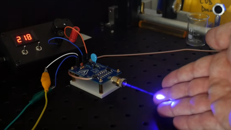
For testing, [Les] used a high-voltage supply homebrewed from a Nixie inverter module along with a function generator to provide the pulses. The driver was able to push 80 amps into a Nichia NUBM47 diode for just a few nanoseconds, and when all the numbers were plugged in, the setup produced about 67 watts of optical power. Not one to let such power go to waste, [Les] followed up with some cool experiments in laser range finding and dye laser pumping, which you can check out in the video below. And check out our back catalog of [Les]’ many laser projects, from a sketchy tattoo-removal laser teardown to his acousto-optical filter experiments.


I’m not going to be the laser safety nanny here,
except in the way of burning out a diode laser with too much current.
That’s a fear that I have from the early 1990s when diode lasers were around $80 each.
Yeah, I still haven’t gotten over the “Do NOT get fingerprints on LCDs!” mentality of that era…
Seems if one really needed power, they’re be better laser types to dump it into. Maybe something from the “dangerous chemicals” department.
They are surprisingly robust with these short pulses. I wrote an article for LaserFAQ about ESD and catastrophic optical damage years ago and never guessed you could reliably drive them like this!
Are you referring to Sam Goldwasser’s Laser FAQ?
(Thanks for your response!)
The very same, specifically this article: https://www.repairfaq.org/sam/Blu-ray/site1/
I’m kind of curious. Is this similar to the driver that would be used in a rail gun ?
That’s just a transistor that’s able to resist high voltage and large current. It’s not able to dissipate a lot of heat (the package isn’t made for this), so this mean very very very small duty cycle. Your rail gun will need mechanical time frame (in the order of ms, not ns), so you’ll very likely burn the transistor on first try. You might want to look at better transistor, with SiC for that kind of power dissipation.
So what piece of equipment was Les using to generate the 6.97 nano second pulse width at a repetition rate of 5000 Hz
The avalanche generator triggered by a function generator is explicitly described in detail in the video.
A transistor driven in Avalanche mode. Some can have super fast rise times, on the order of picoseconds. Look up the Jim Williams Avalanche circuit, very useful for testing oscilloscope bandwidth.
Here’s some links!
https://hackaday.com/2013/08/06/avalanche-pulse-generator-design/
https://hackaday.io/project/2226-avalanche
https://www.eevblog.com/forum/projects/yet-another-fast-edge-pulse-generator/
I meant the arbitrary function/waveform generator. It did not appear in the video.
In the video he states that the function generator was producing 1-microsecond pulses. This doesn’t seem like a big challenge.
The literature recons they’re good for multimillion shots, but testing should be done.
Great to see you here Les. That’s fantastic work, well done and well presented.
An irony is that an application you reference (optoacoustic imaging) really prefers longer pulses, to better excite the acoustic frequencies of interest: Around 100 ns, well within the capability of a linear driver, which then enables non-trivial modulation schemes like chirps, Golay sequences, or Gold codes. These, after demodulation, enable far higher signal-to-noise in the received optoacoustic signal. It also permits using conventional LEDs, since you also don’t need the collimation possible with laser light — a typical optoacoustic application illuminates a relatively large patch of tissue.
Thanks!
Same with the Dye Laser article as well. A pump pulse on the order of about 200nS is preferred for that, I was just curious how far it could be pushed.
Nice, it sounds like you have worked on this stuff before. I did see something about pulsed LED’s for applications like this, and it would be pretty interesting to run one off the driver and characterize it.
A fun thing to try, to demonstrate photoacoustics, is to put a patch of lampblack or india ink on a shiny piece of sheet metal (or even a white card). Turn your frequency down from 5 kHz to something more audible like 800 Hz, and interrupt the beam with the painted target, alternating between the dark patch and a non-absorbing area: You can clearly hear the difference between the absorbing and the reflecting areas on the target. It is obvious at the microjoule level, but probably is still audible into nJ territory. It works with LEDs too. (And xenon tubes, but that’s obvious, even if you don’t recognize it as a photoacoustic pop.)
(Comment from Les, then Paul, why am I suddenly thinking about guitars?)
Sorry. Dunno about Les, but mine is a Fender Stratocaster.
The early laser diodes had to be driven this way. They wouldn’t lase at the modest currents they could take continuously. So a transistor in avalanche mode was the way to go. For example, from 1975:
https://www.worldradiohistory.com/Archive-Poptronics/70s/1975/Poptronics-1975-07.pdf
See the Forrest M. Mims article on page 39.
Absolutely! I remember those diodes Very odd looking packages that were threaded on the outside, with a single pin connection. If fact, ha! I see it on page 44 of the article you have linked! Fantastic! I really do love and miss this old stuff! :-)
Light travels about 30cm per nanosecond, so how come the visible “pulse” artefacts seen in the long exposure are only a few mm in length? There’s something else going on to produce that effect which can’t be related to nanosecond-timescale events.
I was stuck on that, too… My ultimate guess was that he waived a card (once?!) through the frame during a long exposure. Still, it seems like it would be difficult to get right!
I’ve thought about it for a moment, and here is my best guess. You are correct that light travels at 30 cm per nanosecond, but the pulse stops when it hits the paper producing a visible spot. If you move the paper in front of the laser it’s a function of the pulse frequency of the laser and the speed the piece of paper.
I don’t know how fast you can move a piece of paper, but we can do a back of the envelope calculation. If we want a visible dot every 1 mm, with a laser pulse frequency of 5 kHz, you have to move the paper 1 mm in 1/5000 of a second, or 5 m/s. Which sound very possible.
The length of each dot is determined by how fast the paper travels while the pulse is on. At 5 m/s, and a laser pulse of 1ns, the paper only moved 5nm, which isn’t a lot.
Warning: Do not touch laser with remaining fingers.
You can touch the beam, though. That’s just light.
Depends on cooling for the most part. If he fashioned a liquid cooling collar for it and was actively pumping heat away from the diode so that it could operate within its prescribed heat ratings (which shouldnt be hard since it is pulse modulated which helps reduce heat quite a bit), it could operate with negligible harm to the diode.
No. At this duty cycle, there is negligible thermal concern.
What kills a laser at these peak powers is ablation and destruction of the reflecting surfaces that form the cavity. The incident power density on these mirrors is many times greater than the surface of the sun (for those few nanoseconds). Once the slightest bit of damage to the surface happens to degrade the mirror, it’s a runaway process, instantly destroying the mirror and stopping the laser process: The bright laser turns into a dim LED.
That’s exactly what we in the industry call the dark line defects. It’s like a spider web growing from the quantum well and creeping around the laser facet and stretches down the laser cavity until you hit a catastrophic failure and get an exploded facet (< 2 um in size). A lot to do with materials used for the laser. Purity and some material properties themselves. We identified some of the defects came from having Aluminum so the entire company was formed around this Aluminum free laser idea. We had a good run for over a decade but the company is no more.
Cool.
Now, what would happen if we had an array of these lined up to feed a beam combiner?
Assuming we got everything aligned tight enough to cut/engrave with it, would it be better to have each diode pulsing at the same time, or in sequence to give the same effect of a continuous beam?
Would an array of ten of these amped up diodes be more efficient than just a 100w tube laser?
As always, would it be worth the effort?