[Julian] knows that real diodes you can buy don’t work exactly like we say they do. That’s actually pretty common. We routinely ignore things like wire resistance and source resistance in batteries. Diodes have problems that are harder to ignore, such as the forward voltage drop. So, while a real diode will only pass current in one direction, it will also drop some of the voltage. [Julian] shows you how you can get simulated ideal diodes and why you might want them in a recent video you can see below.
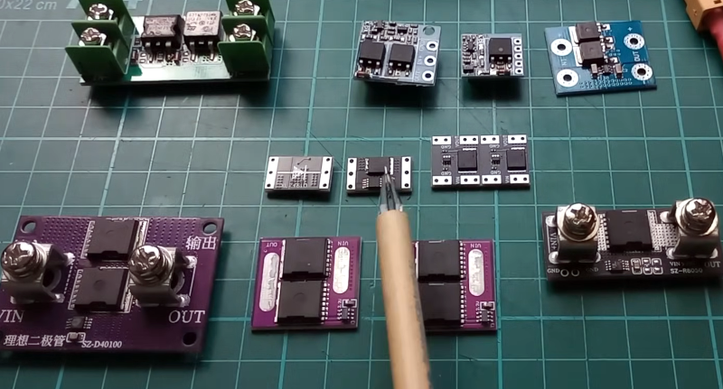
The video starts with a simple demonstration and enumerates some of the practical limitations. Then, he pulls out some ideal diode modules. These typically don’t solve every problem, so they aren’t really ideal in the theoretical sense. But they typically appear to have no forward voltage drop.
The devices use MOSFETs that turn on to have a low resistance when biased forward. Even then, you’ll have some voltage drop, but it can be made extremely small compared to a real diode.
If you don’t need to handle power, it is fairly easy to couple a diode and an op amp to get similar behavior. But where you really want to minimize voltage drop is in power applications, so these modules use beefy FETs.
Some of the modules can float and handle high voltages. Others require a ground reference and will thus have difficulties with higher voltages. The control electronics differ significantly depending on the type of MOSFET used, and [Julian] covers that in detail in the video.
You might want to check out one of our favorite videos on non-ideal diodes. We are guessing that DIY diodes will be far from ideal.


I don’t know anything about these ideal diode controllers so I’ll just ask
Can they be used to deal with the very common multiple power source problem
Example USB and battery providing power to the same circuit, USB power to be preferred over battery power when available, backflow not allowed to either
Its amusing how the simplest solution to this problem is still normal diodes. But if you don’t want the drop… It gets a lot more complicated very fast
I probably know the answer to this already but these ideal diode controllers aren’t made for switching applications, right? I mean there’s no way they can manage to get even a fraction of the reverse recovery time of a schottky diode, right?
We are using them on the V2 Smoothieboard to handle the multiple 5v inputs.
https://github.com/Smoothieware/Smoothieboard2/blob/CcecilMods/V2_P11_Prime2660/smoothiev2-prime-2660.pdf
Sheet 7 of that schematic shows the one used.
That’s a neat circuit, quite simple too!
Thanks for letting me know of this.
has also been used on raspberrypi
https://robotics.ong.id.au/2014/07/30/raspberry-pi-b-power-protection-circuit/
When using them for power path applications, be sure to check the quiescent current. 500uA is not uncommon. It may be unacceptable for battery lifetime.
These Ideal diode modules tend to be very slow. They will not work for switch mode power supplies.
If you want an ideal diode in your SMPS, look for one with synchronous rectification.
They won’t work very well at switching speeds (unless you make them with very expensive opamps), but you can still use them to replace the mains bridge rectifier in switchmode supplies. You’ll be saving a TON of dissapated power in the rectifier, especially in high-power supplies (100W+).
I use them in my linear bench supplies to stand in for bridge rectifiers (LM393 plus cheap 50A switching FETs). From 200W+ power dissapated with a standard bridge, to just under 20W total with ideal diodes (and that is peak power dissapated, not RMS).
200W dissipated in a bridge rectifier, that’s ~150A. That would be a huge powersupply and 50A FETs wouldn’t do, none of those numbers add up
In reality, it depends a lot on the ESR of your bulk DC caps, but no…not 150A, but around 50-60A in my case (peak – the current into your bulk DC caps are not sinusoidal – the diode only switches on at around 0.6V “above” the DC cap voltage). This is a 40V, 5A linear supply.
so 50A and bridge would be ~70W peak and much less average
You might want to check out power path controllers, they use mosfets as ideal diodes but are more tailored to the problem you describe
https://www.analog.com/en/resources/technical-articles/primer-on-powerpath-controllers-ideal-diodes-prioritizers.html
Look up LM66200DRLR
or LTC4451AV for wider voltage range and higher current.
Point is, there is an electronic part called “Ideal Diode”, very handy to use, I’ve only learned about them quite recently.
You can get dedicated ICs for that now. They can take multiple inputs and automatically select which to use based on criteria you program into them, like voltage, priority, etc. So if you had a battery connected you could choose to have the battery discharge to a certain level before you switch to one of the other power inputs or you could do exactly what you described where you have one port as priority so if you have USB power then it is always used instead of battery power.
For a 50/60 Hz bridge rectifier, a semi-passive circuit using 2 Schottky diodes and 2 MOSFETs can keep the drop below a few 100 mV. e.g. see https://github.com/kopchik/semi_active_rectifier . Note that the MOSFETs appear to be in reverse, but are correct.
Note also that you can’t replace the schottkys also with MOFETs because it won’t peak rectify.
LT4320 is also worth mentioning in this context. It’s an 8-pin IC that forms a bridge rectifier when combined with 4 N-channel MOS-fets.
I’ve used a pair of ideal diodes to allow paralleling an external Lithium battery pack with the internal battery of my electric bike. The ideal diodes do the job perfectly without getting even slightly warm due to the low voltage drop. Be sure to check that the specs match your needs. I used a device that require a ground connection due to the switching issue mentioned in the Julian Ilett video.