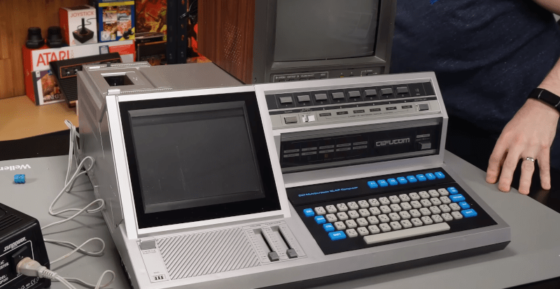
[Ctrl-Alt-Rees] bought something strange on an auction site: a Japanese Cefucom-21 from 1983. No? Didn’t ring a bell for us either. The legend on the front boldly proclaims: “CCI Multipurpose SLAP Computer,” so maybe it is some kind of computer, but it is definitely strange. For one thing, the “screen” isn’t a screen at all. [Rees] has found that it has something to do with teaching English. You can see the odd beast in the video below.
We don’t know how common these were in Japan, but they appear to be virtually unknown everywhere else. Inside is a Z80 computer based on a Sanyo PHC-25, which is a little better known.
The strange screen is offset from the keyboard. There was also a tape drive and a ROM cartridge port. The screen, however, isn’t driven by the computer — you still needed a TV. Instead, it is a window to view a paper graphic stored on a special kind of cartridge. The cartridge simply had images printed on paper. The computer could roll the paper to an image.
Inside, the computer is a fairly conventional Z80 design but with many extras, including a second Z-80. Luckily, the battery, which is known to leak, didn’t completely blow out.
When the video was made, the old box wasn’t working. However, a comment on the video indicates that he’s since got it working and found the software for it, so we are looking forward to a hands-on video soon.
Have you seen one of these before? If you have, we are sure [Rees] would appreciate hearing from you. There seems to be a correlation between odd machines and dual Z-80s. We love seeing these old, forgotten machines.


i thought immediately:
Quite strange to see a flat screen / square edges for a CRT in 1983. There weren’t any at that time.
“The computer could roll the paper to an image” what an awful wording !
Winter’s city-side
Crystal bits of snowflakes all around my head and in the wind…
Sorry guys, but the song is catchy and came to me as soon as I did read the title. For those interesting in an instant blast of energy that makes goose bumps I recommend the live version in Москва: https://www.youtube.com/watch?v=SrZArIrYXJY&t=911s minute 25:28 and turn volume up.
OK Ok no more offtopic,yeah the machine is cute.
I was afraid no one would get it…
To be fair, it is a screen, it’s just not an electronic display but rather a literal paper display.
you´re 100% right. Accuracy is getting lost in nowadays babble-garbage :(
interesting machine. the paper roll graphic display could make for a cool retro tech display in a moody movie, a la the scene in mr robot with the C64 and Angela.
I did a cursory disassembly of the firmware. I was unaware of the Sanyo device, but that tracks as the BASIC system is 24 KiB ROM and there is a 6 KiB region that looks like screen stuff @ 6000h.
The ‘system’ board seems to be port i/o mapped, not using nmi, using int, 32 KiB memory. It doesn’t use nmi, but does use int, which is interesting because I’m not seeing an instruction switching to IM1, which is a necessary action. So maybe rom 4 is paged in and does that. I haven’t looked at that rom closely yet.
I/O seems to be port based. I can see 40h fiddles some bit; b3 is clearly a strobe of some sort, and 00h seems to drive a latch.
The second board has more rom, much less ram, a boatload of peripheral chips (mixing 8255s and Z80 PIOs, which is striking), so I think that is the ‘i/o’ board. I didn’t dig deep into those roms yet, since without schematics I will be limited in what I can infer from the code. Plus, I think it is functionally a peripheral of the “MCU02” board.
I did find the BASIC error code display routine, which should make short(ish) work of resolving the display stuff. It’s been a while since I saw a 684x. I though mapping the keyboard matrix without a schematic would be stimulating, but your mention of the known Sanyo device might make that easy. Oh well, there goes the challenge. But it was fun while it lasted….
You could probably code-LEGO it together in no time using the existing framework and devices provided by MAME.
possibly; that might answer some of the general hardware questions, like the keyboard matrix, but I do like my challenges.
Also, this unit is an augmented Sanyo with other hardware, and patches to the original firmware. E.g. I figured out that rom 4 fits in the 2 KiB hole at 7800h, and the board ties A11 low. This added rom is thunked over to during cold boot, and IM2 is set up for the addition of the PIO that apparently wasn’t in the Sanyo (which clearly was an IM1 system, because rst38 is still there and does meaningful stuff. The PIO A isr does it’s thing and thunks over to rst38 to finish up.) There’s some nop’ed code in cold boot init that might have originally done the IM1.
The IO board is something else, but maybe I have the roms in the wrong order.
It’s Halloween let’s see some gore!
What a offal sight, the damage created by one of those Varta chemical time bombs. I service a brand of Italian made organs that have those on board battery backups. The chemical goes through traces, vias, sockets, roms, and right into the die—die. Traces on the board rot and flake off. Prepare to isolate and rewire former traces and replace every IC within the zone. It’s usually near the reset, ROM, and clock circuits so that will kill it for sure. Remains will continue to eat metal, clean and scrape away all that vampire blood.