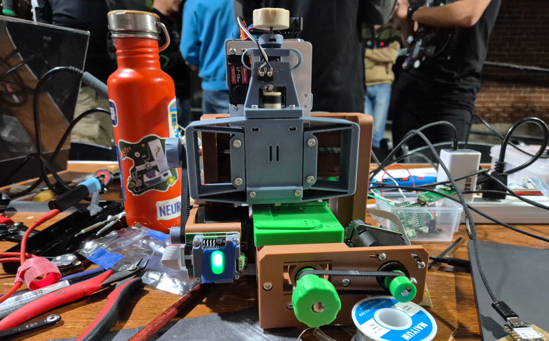
Walking around the alley at Hackaday Supercon 2024, we noticed an interesting project was getting quite a bit of attention, so we got nearer for a close-up. The ‘Circuit Graver’ by [Zach Fredin] is an unconventional PCB milling machine, utilizing many 3D printed parts, the familiar bed-slinger style Cartesian bot layout and a unique cutting head. The cutting tool, which started life as a tungsten carbide lathe tool, is held on a rotary (‘R’) axis but can also move vertically via a flexure-loaded carriage driven by a 13 kg servo motor.
The stocky flexure took a lot of iteration, as the build logs will show. Despite a wild goose chase attempting to measure the cutting force, a complete machine solution was found by simply making everything stiff enough to prevent the tool from chattering across the surface of the FR4 blank. Controlling and maintaining the rake angle was a critical parameter here. [Zach] actually took an additional step, which we likely wouldn’t have thought of, to have some copper blanks pre-fabricated to the required size and finished with an ENIG coating. It’s definitely a smart move!
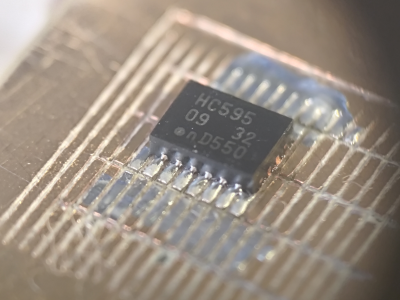
To allow the production of PCB-class feature sizes compatible with a traditional PCB router, the cutting tool was sharpened to a much smaller point than would be used in a lathe using a stone. This reduced the point size sufficiently to allow feature sizes down to 4 mils, or at least that’s what initial characterization implied was viable. As you can see from the build logs, [Zach] has achieved a repeatable enough process to allow building a simple circuit using an SMT 74HC595 and some 0402 LEDs to create an SAO for this year’s Supercon badge. Neat stuff!
We see a fair few PCB mills, some 3D printed, and some not. Here’s a nice one that fits in that former category. Milling PCBs is quite a good solution for the rapid prototyping of electronics. Here’s a guide about that.


Seems we’ve re-discovered the idea behind “Shaper” machines.
Learning what tool point geometries and feed velocities give the smoother cuts in a chosen material can be a large curve. Check around for older machining books, World War 2 era, should be some good basics to start with.
ahh. I forgot to mention “single point thread cutting” The tooling for that process is going to be more closely related to this.
Yeah this project is certainly inspired by shapers and hand gravers and many other machines from the past, just applied to a novel substrate. A real challenge here is material heterogeneity; thin copper foil over fiberglass isn’t really comparable to steel, so the cutting parameters are dramatically different and need their own parameter study to understand. But the methods used in history to run those studies are still quite relevant! If you have any recommendations for old machining books that you think are relevant, I’d be into checking them out.
Do you know what grade of carbide you were using? For cutting copper, which is soft and gummy (in a relative sense) sharpness matters. It’ll help cleanly cleave the copper with less tearing along the edge of the cut. Micro or nanograin carbides can take a sharper edge than standard grades. Wood turning tools can be an accessible if pricey source if you can’t find them at industrial suppliers.
I first thought of high speed steel as the cutting material of choice for this, but I’m not sure how it would handle the abrasiveness of the FR4.
For tool geometry, a tool with a chipbreaker that slopes in towards the center of the cutting tip should help. You basically want the chip to fold towards the center of the cut from 3 axes (left, right, below).
You might look at aluminum specific inserts. They’re available in micro grain, honed, and with a built in chipbreaker.
Good luck! It’s really cool to see shaper (or maybe planer?) tech applied to circuit boards.
That’s a great question. This is the Mitsubishi insert I’m using, mostly chosen for its 0.1 mm tip radius which I’ve taken to sharpening with a diamond stone: https://mmusec.mmc-carbide.com/products/267995
The material is advertised as HTi10 uncoated carbide, which some web searching suggests is suitable for non-ferrous alloys, but I’m not sure how small the grains are. I’ve been flattening off the chip breaker too, because otherwise I only got reasonable cuts with a ~15% positive rake angle; I think that might be related to the springiness of the Z-axis since it’s operating in pressure-control rather than position-control mode.
I talk about this a bit in the talk (which will eventually be posted, once Hackaday gets the videos sorted), but I think the real next step for this project is a deep dive into cutter geometry and material, maybe assisted by a much stiffer and instrumented machine for testing. Chip production is probably weirder than we think, since the material is layered and the fiberglass is heterogeneous.
Thanks for the comments! I’ll keep looking for other inserts to try, too.
Chip formation is likely to be flat out weird, with a heterogenous material formed of a homogeneous top layer and a heterogenous substrate having variable local hardness and isotropy.
The chipbreaker probably caused problems cause it’s an R (right handed), an N (both sides) chipbreaker would probably help. If you’re up for changing insert geometry, a T (60° triangular) insert is more likely to be available with an N chipbreaker.
I did a little digging for inserts and ran into the problem that most metal inserts don’t have much information about carbide grain size, and most wood turning inserts don’t have much information about anything but carbide grain size. Sigh. That being said, if I were working on this I’d be tempted to try this insert from woodpeckers https://woodworkersworkshop.co.uk/woodpeckers-replacement-carbide-insert-universal-detail-sharp/ and grind in a 2 sides chipbreaker with a diamond wheel in a Dremel.
I see that the people with much more up to date information have arrived, thankfully!
Any books that I had, were from the 1960~70’s and long gone now and a fair bit of specifics are fading from my unused mind now. an old fart hoping to trigger some discussion from the currently active folks mostly.
I’m glad to see that at least there are other readers are on the ball with answers though.
The low noise level and low dust output, compared to a mill.
PS: The video is not publicly listed on the channel.
What’s wrong with Proxxon mill converted into a CNC? Ah yes, a distinct lack of 3D printed farts.
Nothing – we’re talking about this project atm. This setup seems less dusty and is a nice project to tinker on.
This project demonstrates a fundamentally different cutting process with a different set of limitations and advantages. Milling circuit boards has its place (and I mill PCBs pretty often), but it’s noisy and has trouble with the fine details needed to use modern parts. But sure, retrofitting a stiff steel mill with CNC gear is another path; I wanted a project that was better suited to my apartment, and yes, I wanted to build a thing that was mostly 3D printed.
I have one of those aluminum toy cnc engravers, doing pcb’s on them is great, but it sounds like a sack of cats tossed into a blender and about as messy too
“Slicing” the cheese?
Can I make these 3D-printed farts in any 3D printer?
Can it drill holes too though? Single sided PCBs can be pretty limiting.
can probably scratch one, but it’s obviously the wrong tool here.
No; this process shares the same limitations of other home-gamer techniques like milling and etching. But I think there is still a worthwhile space it can fit, like to make simple breakout boards for interesting tiny parts.
I would gladly buy such ENIG-coated blanks for CNC use.
Even better if there were blanks coated first with ENIG and then with soldermask, so you can have both and then test your Z-height accuracy when trying to mill away the soldermask :)
Cheap PCB manufacturers will put a heavy extra fee if you order a big plate that’ll be fully ENIG coated.
I got them from OSH Park! I just poured copper and solder mask on both sides of a cutout in KiCad and submitted the Gerbers as usual. An interesting bit: I also had PCBWay quote the project and it was initially quite a bit cheaper, but after the engineering review they updated the price to be roughly the same as OSH Park’s medium run service. I’m guessing it’s because of the much larger ENIG area or something. Ended up being around ~$1.50/coupon at qty ~50.
I expected something with a router or other kind of fast rotating tool, but this is way cooler! A challenging build I assume, plenty of forces to withstand. So to see such an accurate result is very promising. Cool project, I like the “out of the box” thinking here.
thanks! I included the fab files and original Fusion repo in the project; I encourage you to print/build/remix if you feel like it, it’s a fun excuse to play with flexures.
First one! I have made this some time ago, but not published yet. No need head rotation, no special instruments, just used bit from cutting plotter and regular CNC like 3D printer. Coming soon https://imgur.com/a/RwRdv00
Zach stated in his talk at supercon, that the 4th axis came from “my friend needed something with 4 motors to control”, so that why the head is rotation. That can be super useful for other things probably.
Oh this is fabulous! Please send a note when you publish, I’d love to take a look at your project. I never tried just using a passive drag knife but it’s neat to see that seems to work. As Dave mentions, part of this was an excuse to build a 4-axis machine for the fun and complexity of it.
I was very lucky to be at the supercon presentation, I hope the designlab videos wont take too long to drop! Zach’s energy and joy on stage sold this thing to me – actually way before at the Friday gettogether. Always fun to see Zach’s projects and I’m happy I had the chance at supercon!
<3 thank you friend. Was so great to catch up!!
Not sure why I think about such things but…
You could pop out the cutting tool and replace it with something of similar hardness to Keratin and a piece of slate in place of the PCB. Then invite everyone to come see your creation as you activate it.
Just for fun then put it back.
The actual use, making PCBs… that’s cool. Good job!