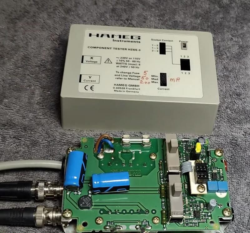
In the modern age, when you hear “component tester” you probably think of one of those cheap microcontroller-based devices that can identify components and provide basic measurements on an LCD screen. However, in the past, these were usually simple circuits that generated an XY scope plot. The trace would allow an experienced operator to identify components and read a few key parameters. [Thomas] tears down an old Hameg device that uses this principle in the video below.
The unit is in a nice enclosure and has a feature that controls the amount of current the unit uses in the excitation signal. It plugs into the wall, and you can connect the component under test with either test leads or a socket. The output, of course, is a pair of BNCs for the scope’s X and Y inputs.
Compared to some homebrew projects that are similar, the PCB inside the device seems more complex. The output of most devices like this uses the line frequency (50 or 60 Hz). This one, however, has its own drive oscillator that operates at a different frequency.
Each type of component has a tell-tale trace on the scope. We found the tunnel diode trace especially interesting. Capacitors are circles, diodes make a definite step shape. There’s a table from the manual near the end of the video.
Most of these devices are much simpler, using a transformer to generate the AC sweep and a simple mechanism to measure the current. That makes them quite easy to build and they are still surprisingly useful.


So, it’s a curve tracer?
but also a very poor tear down
I use a similar unit every day at work hunting for bad components in 80-90’s mil-spec circuit cards. I have both a old Huntron 2000 and a ‘chinatron’ (Chinese ebay clone similar to this Hameg style unit) hooked up to Tektronix 2235. In this video I like the signature card he shows as it shows signals when combined in circuit with other components. Since your testing everything in circuit first, only when you get the ‘black sheep’ signal you pull it out of circuit to verify the signature behaviour. From that point you determine is the part tested the problem or is it another part in the circuit and the ‘hunt’ continues. Thus the name ‘Huntron’ as you are literally on the “hunt” for bad elec”tron”ics components. We rarely get any failure data or a ‘known good’ board to test against, so its going into circuits blind. These component testers are an absolute must for this kind of work. Great video!
I bought a Huntron BugHound for $2 several decades ago, I need to get around to replacing its leads.
Yep, it’s a bog-standard 2-wire curve tracer.
Google ‘octopus curve tracer’ to see how to make your own.
It is nice to see how real companies make them though. It’s been in the back of my mind to make one for fun for a while now.
Very poor tear down in all honesty.
I had one built into a Bell&Howell (Heathkit) oscilloscope that a neighborhood ham gave to me when I was just a kid interested in electronics. It was just extra banana plugs neatly added with no labels, but he showed me how to use it. I remember inductors gave an interesting ringing display. Since I sourced my components from old radios and TVs it was useful to find good parts. Oh yeah, this ham always had good giveaway stuff. His buddies would enroll in the B&H electronics course and he would complete the course for them. They didn’t learn anything but got the “free” color TVs that he built, and he got all the test equipment kits.
Read the article and the comments, and excitedly clicked on the link in the article to check out the “curves of components in circuits”…. only to be greeted with a youtube link. Immediate click ‘close tab’, write a comment here, and next is to click off.
I’m absolutely sick of ‘yet another youtube unboxing video’ (well, not quite, but from other comments, it doesn’t sound like it’s too far off).
I’m OVER it!
If you prefer a poorly written blog post, here is my offering:
http://levysounddesign.blogspot.com/2016/04/octopus-tester-component-curve-tracer.html?m=1
This is why I come to Hackaday! Thanks for posting bigredlevy :-)