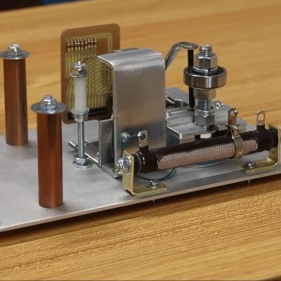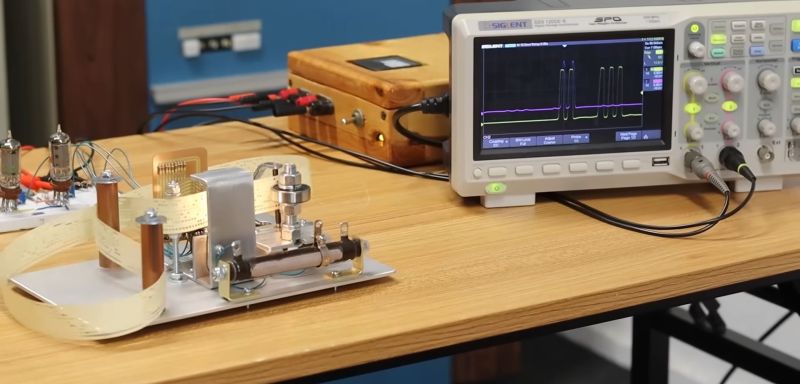
On today’s installment of UE1 vacuum tube computer construction, we join [David Lovett] once more on the Usagi Electric farm, as he determines just how much work remains before the project can be called done. When we last left off, the paper tape reader had been motorized, with the paper tape being pulled through smoothly in front of the photodiodes. This left [David] with the task to create a PCB to wire up these photodiodes, put an amplification circuit together (with tubes, of course) to amplify the signal from said photodiodes, and add some lighting (two 1-watt incandescents) to shine through the paper tape holes. All of this is now in place, but does it work?
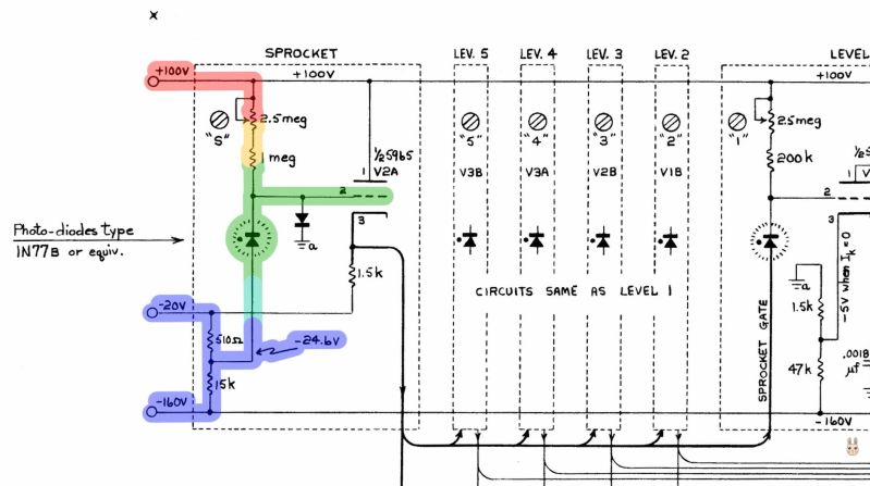
The answer here is a definite kinda, as although there are definitely lovely squiggles on the oscilloscope, bit 0 turns out to be missing in action. This shouldn’t have come as a major surprise, as one of the problems that Bendix engineers dealt with back in the 1950s was effectively the same one: they, too, use the 9th hole on the 8-bit tape as a clock signal, but with this whole being much smaller than the other holes, this means not enough light passes through to activate the photodiode.

Here, the Bendix engineers opted to solve this by biasing the photodiode to be significantly more sensitive. This seems to be the ready-made solution for the UE1’s tape reader, too. After all, if it worked for Bendix for decades, surely it’ll work in 2024.
Beyond this curveball, the rest of the challenges involve getting a tape punched with known data on it so that the tape reader’s output can actually be validated beyond acknowledging the presence of squiggles on the scope display. Although the tape guiding mechanism seems more stable now, it also needs to be guided around in an endless loop due to the way that the UE1 computer will use the tape. Much like delay line memory, the paper tape will run in an endless loop, and the processor will simply skip over sections until it hits the next code it needs as part of a loop or jump.
With semi-modern components, paper tape is easy to handle. Automatic tape feed only adds a little complexity.


About a clock bit problem, you might try mechanical solution. Use stronger light source, and make a mask between a light and paper tape, with holes not larger than clock holes on tape? That way all diodes would get same amount of light.