Interesting parts make for interesting projects, and this nifty precision voltage reference has some pretty cool parts, not to mention an interesting test jig.
The heart of [Gaurav Singh]’s voltage reference is an ADR1399, precision shunt reference from Analog Devices. The datasheet makes for pretty good reading and reveals that there’s a lot going on inside the TO-49 case, which looks unusually large thanks to a thick plastic coat. The insulation is needed for thermal stability for the heated Zener diode reference. The device also has a couple of op-amps built in, one that provides closed-loop voltage control and another that keeps the internal temperature at a toasty 95°C. The result is a reference that’s stable over a wide range of operating conditions.
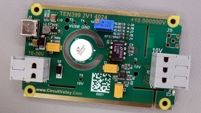
[Gaurav]’s implementation maximizes this special part’s capabilities while making it convenient to use. The PCB has a precision linear regulator that accepts an input voltage from 16 V to 20 V, plus a boost converter that lets you power it from USB-C. The board itself is carefully designed to minimize thermal and mechanical stress, with the ADR1399 separated from the bulk of the board with wide slots. The first video below covers the design and construction of an earlier rev of the board.
One problem that [Gaurav] ran into with these boards was the need to age the reference with an extended period of operation. To aid in that, he built a modular test jig that completed PCBs can be snapped into for a few weeks of breaking in. The jigs attach to a PCB with pogo pins, which mate to test points and provide feedback on the aging process. See the second video for more details on that.


Cool project! I’ve been stuck in the past using the lm399. Definitely going to check out it’s evolved form.
Needs to be constantly powered?
It is recommended to constantly Power reference as they develop very very minute change every time to power down and power up.
This board has dual power for transport and backup power. Can be powered constantly not really needed.
On itself, a nice project, but I don’t have much confidence in it.
When using good parts (ADR1399 costs USD 23 LT1001 is USD 2 to USD7 depending on the version) you also have to pay a lot of attention to the rest of the circuit. The potentiometer is the first thing that makes me frown a bit. That it’s labeled “trim generic” in the schematic (and with no value in the schematic) is also sub optimal. On the PCB, It’s “102”, I.e. 1k. For an adjustment pot I would have preferred a much smaller adjustment range (It’s in series with a 20k resistor).
For the rest, he never mentions anything about the type of resistors used. It’s easy to adjust the output of a gadget like this to 10.000000V once, but It’s a quite different thing to design the circuit in such a way that it will stay 10.000000V. Drift is the biggest enemy of voltage references, and you need to use very stable resistors to minimize drift. Because of this, it’s much more common for voltage references to use fixed elements in the amplification section, and then simply print on the box what the actual output voltage is (for example 10.032482V).
The feedback resistors with the jumpers also look arbitrarily chosen. (although they’re roughly a factor of two in value difference)
An (option for) battery power (and monitoring) would be nice for a circuit like this. Could be very simple with replaceable batteries, or more elaborate: Charge 4 or 5 Lithium cells in series via the USB connector, and a monitoring circuit to keep track of battery charge conditions.
I’m also just a hobby guy. One thing really missing is a link to the metrology section on the EEVblog, with comments from people much more knowledgeable then me.
I haven’t gone over his design yet, but I would assume he’s put some thought into this design. He has some pretty impressive projects on his website, and I have bought some boards from him before. His designs have lived up to what he advertises from my testing so far. It would be interesting to see what the EEVBLOG guys think about it, although it seems like they’re more interested in the LTZ1000/LTZ1000A/ADR1000 at the moment since it is the king of references.
How sensitive is that precision reference to vibration?
What’s the resonant frequency of that cantilever arm that it’s mounted on?
There are Two version of this reference. V1 has pot while V2 does not have Pot but has Solder jumper resistors
V2 of board in Various Configuration is available on tindie.
https://www.tindie.com/products/circuitvalley/adr1399-10v-precision-voltage-reference-calibrated/