The Cheap Yellow Display may not be the fastest of ESP32 boards with its older model chip and 4 MB of memory, but its low price and useful array of on-board peripherals has made it something of a hit in our community. Getting the most out of the hardware still presents some pitfalls though, as [Mark Stevens] found out when using one for an environmental data logger. The problem was that display, touch sensor, and SD card had different SPI busses, of which the software would only recognise two. His solution involves a simple hardware mod, which may benefit many others doing similar work.
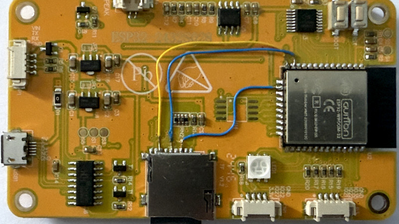
It’s simple enough, put the LCD and SD card on the same bus, retaining their individual chip select lines. There’s a track to be cut and a bit of wiring to be done, but nothing that should tax most readers too much. We’re pleased to see more work being done with this board, as it remains a promising platform, and any further advancements for it are a good thing. If you’re interested in giving it a go, then we’ve got some inspiration for you.


Awful. What is the benefit over a software solution?
Negative Ned
Have one of these sitting on my desk right now. Cool little hack. My question is, what was originally supposed to populate the U4 chip footprint. Looking at the traces, it has VCC/GND, an at least three of the pins lead back to pins on the ESP32. Would be an easy to solder spot to tap those otherwise unused GPIO pins.
I’d have to look at the esp32 pinout, but a guess off the top of my head is either psram or additional qspi flash.
It is meant for PSRAM. There is a hack in the Cheeap Yellow Display repository for getting this working:
https://github.com/witnessmenow/ESP32-Cheap-Yellow-Display
It’s for a flash memory chip, I couldn’t get it to work as it’s built into the esp32 module, however with a bit more hardware hacking you can add a PSRAM chip here which is way more useful. I have turned mine into an old time ZX Spectrum!
It’s for a flash memory chip, I couldn’t get it to work as it’s built into the esp32 module however with a bit more hardware hacking you can add a PSRAM chip here which is way more useful. I have turned mine into an old time ZX Spectrum!
Space is for PSRAM. Lines are the same as for the integrated Flash chip, so they can’t be used for anything else than PSRAM.
Can’t you just as well reconfigure the GPIOs for multiplexed access to different buses? Changing the gpio routing bits takes just a few cycles more than toggling the chip select line, and no soldering needed.
There are three SPI hosts on the ESP32 chip used here, 1 through 3. SPI1_HOST is used and it may be possible to get this working. The default application has SPI2_HOST and SPI3_HOST used for the display and touch sensor.
The Arduino applications used software SPI for one of the interfaces which suggests that this is not a new issue.
But can’t you connect e.g. SPI2 to different pins using the ESP32 GPIO matrix, to access different peripherals? You still cannot access them at the same time though.
The SPI speed would be limited, due to using the gpio matrix. Normally SPI pins are muxed using the iomux, which had a higher speed. But the iomux has very few pin choices, typically just one or sometimes two. So it probably isn’t possible to connect both sets as they were.
You only need to use SPI2 and SPI3. You would leave one of these attached to the touch screen pins at all times, and the other you would attach and detach from the LCD and sensor pins as required. (Reframe: you have two available SPI peripherals; you can have as many SPI buses as you can attach those peripherals to at any time.)
You don’t need any soldering here. This is the benefit of the ESP32’s GPIO matrix.
It’s going to take a bit of work on the software side to get this SPI reconfiguration working elegantly, but the beauty of doing so is that once it’s done it’s done for all CYD boards without anyone needing to heat up their iron.
Would you like to give us an example of this. I looked into doing it ages ago but couldn’t find any information or examples. I gave up and bit bashed it in the end.
“of which the software would only recognise two”
Why? How? Sounds like a software bug. I wouldn’t modify the hardware to fix a software bug.
But not everyone is as good with software.
It’s not a hardware bug, it’s a feature. ESP32’s SPI1 shares data paths with SPI0, which is both used for reading from flash, and where the relevant cache is located. Accesses to SPI1 need to happen from code located in internal RAM, whose critical paths can’t even refer to cached flash data.
It’s a hardware limitation. The esp32 actually has four SPI buses, 0 to 3. SPI0 is reserved for the flash chip the program code is stored on. It has a special connection to the CPU memory bus. SPI1 uses the same pins as SPI0. There is just one value for both in the iomux.
None of the three external spi peripherals were connected to the same pins as the flash chip. So there’s no way any of them can use SPI1. If you muxed spi0/1 to the SD card or display or touch screen, the then you get no program to run because that disconnected the flash chip.
I love all the criticism of the solution from people who didn’t understand the problem.
I learn a ton from the HaD comments, but this is up there on my list of pet peeves.
What started off as a fun bit about “shoulda used a 555” has turned into people heading straight to the comments to be critical.
I had some errors using MicroPython when trying to access the sdcard when the touch screen was enabled. found I could deactivate the touch screen and then access the sdcard. Once I deactivated the sdcard, I was able to reenable the touch screen. Is it possible to have both accessible at the same time without a hardware change?
There is a software solution that worked for me. I found it here
https://github.com/witnessmenow/ESP32-Cheap-Yellow-Display
https://github.com/witnessmenow/ESP32-Cheap-Yellow-Display/blob/main/TROUBLESHOOTING.md#display-touch-and-sd-card-are-not-working-at-the-same-time
I am using the XPT2046_Bitbang library instead of the TFT_eSPI library for the touchscreen. Details and rationale are found in the references above. This seems to work OK with some changes to the code.
You can see my crude adaptation onto the CYD here: https://github.com/Mark-MDO47/UniRemote
More discussion here: https://github.com/Mark-MDO47/UniRemote/tree/master/code/RFIDRC522test#touchscreen-calibration-with-xpt2046_bitbang
I just wanna see someone make it a meshtastic device
CYD is a good board, nut has way too many hardware issues.
– SD card should be connected to MMC controller instead of SPI.
– PSRAM lines are shared with LED making it unusable without hardware mods.
– Light sensor has wrong resistors.
– Audio amp is clipping because of wrong components.
– LCD should be connected to Fast SPI pins instead of some random gpio.
Etc.
If you want a good performance board then CYD is NOT a good choice.
I would like to operate an ArduCAM 2MP Plus (OV2640) on the board. Unfortunately, there is no free access to the SPI bus. The I2C bus is still accessible. Does anyone have any ideas on how to connect the ArduCAM to the board? Thank you very much.