Software Defined Radio (SDR) is the big thing these days, and why not? A single computer can get rid of a room full of boat anchors, and give you better signal discrimination than all but the best kit. Any SDR project needs an RF receiver, and in this project [mircemk] used a single 6J1 vaccum tube to produce an SSB SDR that combines the best of old and new.
Single-tube radios are a classic hack, and where a lot of hams got started back in the day, but there is a reason more complicated circuits tend to be used. On the other hand, if you can throw a PC worth of signal processing at the output, it looks like you can get a very sensitive and selective single-sideband (SSB) receiver.
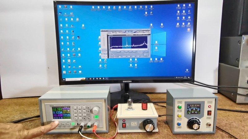
The 6J1 tube is convenient, since it can run on only 6 V (or down to 3.7 as [mircemk] demonstrates). Here it is used as a mixer, with the oscillator signal injected via the screen grid. Aside from that, the simple circuit consists of a receiving coil, a few resistors and a variable capacitor. How well does it work? Quite well, when paired with a PC; you can judge for yourself in the video embedded below.
We’ve featured a lot of [mircemk]’s projects over the years, like this handsome OLED VU meter, or this frequency analyzer with a VFD and even a virtual pinball cabinet made from scraps, among many others.


+1
6J1 is American description for EF95 (EU)/6AK5 (RUS).
The EF95 needs 35v (?) anode voltage to properly work without tricks.
A miniatur electron tube that natively works with 12v anode voltage is EF98, for example.
It was used in car radios and in Kosmos construction kits of the 1960s.
(Here replacing DM300; ECC82 used in 2005 “Radio Ace” kit)
US equivalent type to EF98 might be 6BA6. Russian comparison type might be 6K4P-EV.
A simpler version of EF98 is EF97, also. It tied a grid internally to
to something.
Oops.
Is this just a tube type mixer placed ahead of Alberto I2PHD’s SDR software? In that case it is kind of wrong to call the mixer an “SDR radio.” Especially when the tube-type mixer uses an external (digital) VFO and there are not even quadrature signals (I and Q) from the mixer. Also, it is not clear that the tube-type mixer is doing much of anything — the tuning control seems to just peak the VFO input signal (not the RF coming in from the antenna!). And why does he peak the noise with the antenna disconnected? When he does connect the antenna, we see no increase in noise. That ususally indicates that internal noise generated by the receive system itself is stronger than the external “band noise.” That is not good. Bill N2CQR
It’s an direct conversion receiver, I think.
The SDR software of the early 21th century was using an IF of 7 to 12 KHz.
The famous Dream software for decoding Digital Radio Mondiale (DRM) was using such IF signals, too.
This is a real SDR setup. In early 21th century it was common to use soundcards for demodulation of an IF signal provided by a receiver.
This was years before SWLs had used cheap RTLSDR USB dongles.
So it’s understandable that this setup may not qualify as “SDR” in the eyes of the people who haven’t witnessed the early days of SDR.
I forgot to mention, back in the day we’ve used fixed-frequency crystals
to build a crystal oscillator using a single transistor (BC548) or a tube.
Such as 4 MHz or 6 MHz. They’d go where the VFO input was..
These crystals were close to DRM radio stations (3995, 5995 KHz).
With a small capacitor it was possible slow the crystal down by a few KHz
which was good enough to have an suitable IF came out of the DC receiver.
Oh, and speaking of Dream software..
It was necessary to find an EXE that has the audio codec built-in.
The open source code didn’t cover the DRM codec, that was external.
Users into the hobby also used a programmable PLL instead of a quarz crystal oscillator at one point.
There were some PLLs that had serial input and could be programmed via serial port on PC.
Simple control programs (front-ends essentially) were written in Visual Basic or Delphi at the time. Vy73s
One last thing.. When using a tube in such an SDR setup, it’s not about amplification factor so much.
It’s rather that the tube can handle large signals that, say, a BC548 or 2N2222A can’t.
If you’re attaching a longwire antenna fir reception, for example, the transistors often become deaf.
A tube goes into saturation mode, rather, but still do work.
That’s the rational, practical side of using a tube in modern days.
So, Joshua is saying that the single tube mixer is a direct conversion receiver? I still don’t really see this. You can used phasing type direct conversion receivers (two of them) fed with VFO signals in quadrature to produce I and Q signals that you could send into sound cards in the computer for digital signal processing. That is how they did a lot of the early SDR receivers. That I and Q stuff allowed them to select USB or LSB etc. I don’t see that happening here. There is no quadrature inputting of the VFO, no I and Q out. Nope. If we look at more modern SDR rigs, why on earth would you even NEED the tube type mixer? Just send the RF into an analog-to-digital converter, then to an FPGA to do the DSP. Again, we don’t see that here. And finally, as Joshua points out, the tube would need at least 35 V on the anode. Oops indeed. Is this really the kind of thing that HAD wants to promote? Bill N2CQR
I/Q is nice to have (via L/R line-in input), but not absolutely necessarily for that kind of SDR software. A mic input may do, as well.
The schemtic shown in video seems to be a variation of an earlier one I’ve seen many years ago.:
https://www.elexs.de/ef956.htm
Where the VFO is used to be the fixed-frequency oscillator.
That’s why the variable condenser on other size is no bigger, to because if the external oscillators different range.
PS: The oops was about the nationality of the tube designations only.
6J1 is Chinese, rather than US, for example. I’m not most familiar with foreign descriptions.
About the voltage..Many nowadays schematics run at low voltage by adding a resistor to cathode, grid or something.
It’s a trick to fix the characteristic curve of a tube.
EF95 needs about 30v, whereas EF98 has 24v max or something.
Please double-check datasheets. Thank you. Vy73s
Okay, now I’m writing these lines on a proper keyboard.
What I meant to express was that many modern day tube schematics operate on very low voltages.
They do it for safety reasons, for the inexperienced experimenters not familiar with tube tech,
but also because it allows them to use a single voltage for both heathing and anode.
Using 6v or less is such a case, for example.
By using tricks, a tube that normally needs 35v anode voltage (or more) can be made run with just a single 6v power source.
This does, of course, have an effect of the efficiency of the receiver.
Doing it “properly” will provide a better experience, but that’s maybe not needed here.
PS: Back in the day, it was not uncommon to use the 6v heathers of two EF98 in series,
so that a single 12v power source could be used for both heathing and anode voltage.
That solved the issues in a car, when ca. 12v were available.
Using a linear voltage regulator, such as 7805 was another possbility from 1970s onwards.
But it needs a good heathsink, these heathers draw quite some power. .
(7805 is better than 7806, because even a slightly lower voltage extends tube life.)
“Just send the RF into an analog-to-digital converter, then to an FPGA to do the DSP. ”
Some SWLs did this with the soundcard, but without I/Q signals.
At the time SWLs had good soundcards with 96 KHz or 192 KHz sampling rate and 24-Bit, by the way, not an SB16 or a cheap USB dongle!
For reception, they attached a VLF antenna directly to line-in and tried to decode SAQ machine transmitter.
It worked with SDRadio or SAQ receiver software, for example.
Others do build am VLF to shortwave converter using a mixer IC (NE612 etc).
Then they use an SSB capable shortwave receiver to pick up SAQ.
More information:
https://www.prinz.nl/SAQ.html
Why would you lower RF bandwidth by adding that huge capacitor C5? 4n7+10k is terrible.
Don’t disrespect the tube!
Um, it’s a RC or CRC band-pass filter (C4+R1+C5)?
The 12 KHz intermediate frequency (IF) is wanted by the SDR software, I think.
In pratice, it also worked with as low as 7 KHz, though.
The 1K resistor (R3) is used to make the tube working with 6v.
The usual working point setting is done by C6+R2, I think.
That being said, I’m just an CB radio operator who enjoys the SWL hobby.
There are radio amateurs who can explain this better, I believe.
This is also interesting for history of SDR,
an early DSP based receiver for PCs running Windows 3.1x, ca. 1994.
https://www.am1.us/softwave/#the-softwave-story
It reminds me of the WinRadio series of late 90s.
That was a superhet based technology, though (box/card).
Software ran on Windows 3.1x/95 and Mac OS 8/9 (WR-1550e).