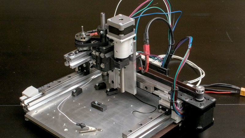
The advent of cheap and accessible one-off PCB production has been one of the pivotal moments for electronic experimenters during the last couple of decades. Perhaps a few still etch their own boards, but many hobbiest were happy to put away their ferric chloride. There’s another way to make PCBs, though, which is to mill them. [Tom Nixon] has made a small CNC mill for that purpose, and it’s rather beautiful.
In operation it’s a conventional XYZ mechanism, with a belt drive for the X and Y and a lead screw for the Z axis. The frame is made from aluminium extrusion, and the incidental parts such as the belt tensioners are 3D printed. The write-up is very comprehensive, and takes the reader through all the stages of construction. The brains of the outfit is a Creality 3D printer controller, but he acknowledges that it’s not the best for the job.
It’s certainly not the first PCB router we’ve seen, but it may be one of the nicer ones. If you make a PCB this way, you might like to give it professional-looking solder mask with a laser.


Why even bother. You can get PCB’s nowadays for less than the electricity it will take to mil your own.
I think you are on the wrong website.
I highly doubt it’ll take 20kWh to mill a $5 PCBway board.
If it was only for the money then yes. For anything else: DIY.
Because you can’t get PCBs in an hour, you can’t fast iterate without at least a week delay, because you might genuinely only want one quick n dirty PCB as a stepping stone to a larger project, because why not have a CNC PCB mill at home and also because it’s fun to build stuff, some people like learning and making tools.
If it’s not your thing that’s fine, we all get our happy in different ways.
While I heartily agree on timing, another serious issue is trusting the manufacturer with the design. If I etch the board, I’m the only one who ever sees my proof of concept. But if I’m not careful picking a fab, there’ll be knockoffs hitting the market before you can say “provisional patent.” Or worse, they’ll patent it first. And sue.
Don’t worry Joe. Nobody is interested in your designs.
I was going to say that but it really depends, ask the people behind the saleae logic analyzer, who’s original design was so simple it should be in a children’s book, or the people behind something like the Sega Dreamcast GDMU.
Almost all the companies I have designed PCB’s for have a “only though these suppliers” policy cause they don’t want their work being posted from JLPCBWAY JIMBOB’s house of who knows who actually makes it (none of them are PCB suppliers they just are brokers)
PCBWay says
“By visiting our site, purchasing something and/ orcustom parts from us, you engage in our “Service” and agree to be bound by the following terms and conditions (“Terms of Service”, “Terms”), including those additional terms, conditions and policies referenced herein and/or available by hyperlink. ”
orcustom (heh professional level contract there bub), plus additional terms provided by hyperlink with no hyperlink
and in section 11
“, You grant PCBWay an irrevocable, non-exclusive, perpetual, royalty-free, fully paid up, worldwide, transferable and sub-licensable right and license to use, copy, modify, reproduce, distribute and display the data” blah blah blah and “By creating an account on the Site, You authorize PCBWay to use Your trademarks, logos, names or signs for marketing purposes.”
pretty boilerplate but still I would not upload any material you consider delicate or sensitive. Blinking LED badge hobby project?
Who gives a FK otherwise, ya you can upload something to one of these Chinese broker sites, and if its something of interest, hell you gave them permission to do what they want with it (and in some cases with a full bom and files to program the durn thing!)
be mindful
As KDawg wrote “You authorize PCBWay to use Your trademarks, logos, names or signs for marketing purposes.” The obvious thing is don’t use trademarks, logos, names or signs unless it is on OHOS project. You don’t have to give them a schematic, or part names (unless you are using their assembly service).
If you use JLBPCB and their full manufacturing and sales listings you can try for a lockout agreement, but such things are worthless anywhere in China. It comes down to finding a company with people you can trust
That’s a valid concern.
But it’s a commercial concern.
A lot, dare I guess the majority of us aren’t doing this commercially.
Not excatly. If you need a special PCB (like thicker copper etc) this may be the only way.
This is a worse solution than a $250 3 axis router.
Belt drive x and y bad.
Most of the z-axis is there, but useless unless you’re skeletonizing the bed.
Linear rails then moved from one end?
The main reason this is a bad idea…single use tool.
Better to build a board holding fixture for cheap router.
At least x and y screws.
But just order board, populated.
It’s not that you can’t do it.
It’s that you don’t want to do it.
Again, only finer pitch and you older.
Get slower, worse result.
Redo twice.
I know ‘hack’ for easy quality circuit boards.
Order them.
Nobody is going from ore + fire to tools to boards.
I can think of at least 2 reasons to do it:
It’s quicker than ordering from China, so iteration is much faster
Because building a machine like this is satisfying and fun
You know the old mantra – If it ain’t broke, fix it anyway. Because you can.
Is it quicker?
Vs. ordering boards populated with pick and place machines.
All comes down to % good boards produced.
Your going to spend hours soldering before you can test.
That’s after you get to a good design, of course.
When working with questionable design also having questionable boards is just great fun (eye twitches).
I’d just order 3, populated as much as economical and KISS.
This is a rabbit hole you don’t want to go down if you’re actually interested in making working boards. The more challenging the board the truer that is.
And yet you completely miss the point. Simple version: this is a DIY built of someone who put quite a lot of time and effort to build something useable, so if you really can’t shut up, then go whining somewhere else.
Second. There are commercial vendors for PCB milling machines. LPKF is one such manufacutrer. These machines have applications where rapid design of iterations of prototypes is important. With such a machine you can make many (10 or more) prototypes on a single workday. There is no out doors PCB service that can do this. And even if it’s just for layout of a PCB antenna, or something like the RF wizardry that is done with PCB tracks in HF applications such as spectrum analyzers or radar systems. The effort may be well worth it.
And even for DIY. Creating a design, and then start soldering your milled PCB half an hour later is quite attractive.
Sure, for series prodution it would be madness to do it this way, but please open your narrow minded mind a bit and try to see over your own limited horizon. You might learn something.
Way to miss the point.
Your not making PCBs, your making populated PCBs. There is nothing attractive about soldering for hours (tiny components) then finding your board has a broken trace or a short somewhere.
A 10% bad board rate makes it insane to fabricate boards at home.
You are adding another unknown, which you already have plenty of.
This a better idea for through hole, but fine pitch surface mount?
Just batshit insane.
If you want to make your own mill, make a better one, that’s generally useful.
Reinventing the wheel, but hackaday. Kids thinking it’s easy to improve designs that are highly optimized, by generations of engineers, is just normal around here.
If you’re actually interested in making boards, stay far away from this.
Using a tool like this imputes a value of your time in the single dollars/hour.
Hours soldering? What are you making? Most projects I see here are a microcontroller plus a few support components.
Apply stencil, swipe paste, tweezer a few components and bake. Where did your hours go?
My own projects…
My last PCB was for combining solar panels. Basically it’s a fuse box with shottkys. Testing a board is 20 seconds with the continuity tester of my multimeter and can be easily be done before soldering anything. If I had a mill I could have eliminated a few weeks of wait time.
No, wait.. months of wait time. I was using terminal strips I had on hand with strange spacing I measured myself and it took a few tries to get it right. At least after the first set of unusable boards I figured out that I should make a board with just my custom parts on it and multiple versions of those rather than re-order the whole board. Figure out which dimensions fit perfect then make the whole board. So.. yah.. months.
Even just milling holes in an old PCB to figure out the perfect spacing for those terminal strips then sending the design to a fab would have been a way better experience than fab alone! But I would need a mill. I’m not going to get sufficient accuracy eyeballing it with my drill press!
My previous PCB project before that was a little board to mount on a 3d printer. It goes from various connectors on one side (for motors, sensors, power sources, etc…) to a ribbon cable on the other. That would have required a bit finer pitch routing but still probably wouldn’t have been much of a challenge.
Again, weeks lost waiting for the order.
I’m not saying I would want to produce a product this way. But the iterations of prototypes leading to one? Or personal projects? Definitely!
A mill is on my to-build list for sure.
Logical extension to that attitude is why bother getting boards, just buy that logic analyser, buy that radio etc etc.
Some people enjoy doing stuff this way and value the learning process.
Agree a ~£150 CNC could do this, but if you do a lot of boards, having a single-purpose machine optimised for PCBs could be worthwhile. Also smaller, which is an important constraint for many of us.
And maybe you’ve got a nice big (but lower accuracy) CNC, so you don’t need a small CNC, you just need something to do PCBs.
Big CNCs generally have great accuracy and expensive nicely concentric spindles.
They have ball screws on x and y. This thing has belts apparently repurposed from a zero contact laser cutter. Spindle could be 3d printed housing around skateboard bearings, hard to say.
The only explanation is:
‘He wanted to make something from parts he had laying about. Didn’t care about actually making PCBs.’
Fair enough.
Good reason.
Bet he now knows why most such machines are bed slingers.
Bet he also wants more Z, to get a second use from it.
Has seen how cheap screws are, said ‘doh’.
His next version will look a lot like a $250 dollar chinesium CNC router (Not the $150 version, he apparently likes Al).
If that spindle is tuneable, then good design.
Throw a dial indicator on chucked up cutter and show us the wiggle.
I’ve seen the outside of outrunner used as pully trick before, in the RC world.
Pick the right motor and RPM is not the issue, offset drive bad idea unless making spindle adjustable.
At that scale, grind the output shaft of the motor true and work from that w precision ground collars.
You do have access a decent surface grinder? (Careful with that machine…Eugene)
That is true. Yet, why would you need custom circuit boards anyway? To make something. This site is for people who like to make things themselves, rather than just buying whatever.
Some like to make their own boards.
“It’s easier to just buy it” could be said about most any hackaday article. Perhaps for a moment you forgot what site you’re on?
There are also some people who really do have good practical reasons for milling their own. Such as when they may need several revisions and don’t want to wait six months to go through a few revisions.
But mainly – this is a hackaday. This site is all about DIY electronics and things. If making things doesn’t interest you, perhaps a different website would suit your interests better.
Ps – for those who don’t want to wait for boards shipped from China and they live in the US or Canada:
Osh Park makes them in the US.
One of those projects where the comments are much more negative then what the build deserves. I quite like this design. It’s more solidly build then a lot of DIY routers, and it has some innovative features that you rarely see, such as the “inside out” timing belt that is used as a flat belt, and just runs on the outside of the outrunner. That’s quite a nice way to get a high RPM on your spindle. I also like the simplicity of the whole build.
I also do not see this as a “Single use tool” as HaHa suggest. Sure, I would never build this machine exactly as it’s presented, but the build is certainly good enough to extend to a 3D printer and a PnP machine.
I would love to see some video’s of this thing running. As others have written here, I also have some doubts about the belt drive, but as PCB milling is usually done with very fine mills, (0.3mm or so for isolation routing, up to around 2mm for the PCB outline) cutting forces are also low. For the rest this machine has enough rigidity so that the axis will move quite linearly without mush sag. He also wrote he choose 400steps/rev stepper motors to increase stiffness (i.e not for the resolution!). This really makes me curious how this machine holds up in use.
The XY stage of this is nearly perfect for a 3D printer or PnP. This asks for having the base plate removable so a higher Z-axis can be added without sacrificing milling rigidity. It also looks like the work envelope is relatively small for the size of the machine. With a few small changes the work envelope can be extended to nearly the size of the working table. But complexity also goes up rapidly with such changes…
Stiffness can also be improved by using a bit bigger timing belts. You can buy Pulley systems with a 1:3 ratio that use quite wide HTD3M (or similar) belts for the “Linear part” and a thinner belt for the gearing loop. These are sold as standard parts and used in (bigger) laser cutters. Both the extra gearing and the thicker and wider belts improve stiffness.
I’ve said it before but it’s important.
You really want to get rid of that PCB dust and not breathe it in. Silicosis is bad.
haha yeah that’s what i thought too…i’m drawn to it because the idea of keeping around some caustic copper-eating fluid rubs me the wrong way….but making a cloud of atomized copper / fiberglass / epoxy might even be worse.
otoh, every tradesman i know has made vast clouds of every kind of dust without wearing a respirator and many of us make it past 50 :)
Agree 100%. So far I’ve only milled FR4 in a pool of water, so there’s no visible dust, and no smell.
This is the way. Also for carbon fiber plate.
Making a small overflowing water-dish thing is a great intro project for the mill too.
The article addresses all these points. It’s not “better” than any of these solutions in general, but is ideal for my usage. Cheap off-the-shelf routers are much bigger and often don’t work well enough (mostly very poor quality spindles and questionable motion systems).
I still order boards, but being able to make some things myself can save weeks of waiting in the prototyping phase.
Thanks for the thoughtful comment.
You’re right that the build area is small relative to the machine, but there really are not many areas where it could be improved without making it bigger, except for cutting a notch into the carriage plate to get about 20mm of X travel.
I’m also interested in improving the stiffness, but I’m not sure about wider belts. I don’t think that’s the limiting factor (10mm GT2 belts are used on much larger machines like the MPCNC), but that’s something that can be measured when I get around to it.
Since writing the article I’ve used it to mill a few aluminium parts, and it works well enough, so it’s not a high priority.
Was going to say similar…except I was going to recommend something like the PCB cutting fluid that PreciseBits sells (very nice people BTW). https://www.precisebits.com/products/chemicals/MELube.asp
They also sell the cutters for PCBs and other things.
I was on the phone with him asking “What pack of cutters would you recommend to have on hand for PCBs?”. His response (like others here) was “Well…with as cheap as PCBs are…you won’t likely need/use them.” To which I responded (as I do to others here) “If it was an end-of-the-world situation…what cutters would I need?”
Having the mill on hand doesn’t mean you need to use it 100% of the time for cutting PCBs. It can also be used for other things.
First alarm bell was the price of the stuff.
Then I had a Duh! moment when they stated you should not eat the stuff after use (@02:00 into their promotion video). So if it triples the life of the cutter, the use of the fluid still doubles the total cost or something…
Right after that they say you cant reuse the stuff, and that was the final alarm bell and I stopped the video.
A 10 second search suggests that regular vegetable oil works reasonably well as a cutting fluid for copper. It’s cheap enough for one time use, but you can also put it in a bottle for a month and let the crud sink to the bottom.
Also: At first I had a frown or two at Antron Argaiv remark about silicosis. Then I read some more background info and silicosis due to glass (dust) is a real issue. Apparently its also relatively common for glass blowers. I guess they get exposed to the dust while glass cutting, and not the blowing itself.
“Then I had a Duh! moment when they stated you should not eat the stuff after use”
Pretty standard stuff, they just say don’t ingest it…I wouldn’t read the warnings on a Skil-Saw if you are triggered by dumb warnings. This is the world we live in. There are reasons these statements are on everything.
“Right after that they say you cant reuse the stuff, and that was the final alarm bell and I stopped the video.”
So…you missed the entire demonstration?
At any rate…I bought some. Thought it was a decent solution to a real world problem.
There are probably several lubricants which “might” work the same. It isn’t a flood or mist coolant though…more like a lotion.
No, I did not miss it, but I did not see it either.
Also this stuff costs: 9.95/.118 = 84.32 per liter. I’m sure it will do the task. Are you willing to accept a simple challenge. Next time use any kind of oil. Even simple sunflower oil is just fine. I predict it will give you 80% of the performance for 3% of the cost.
I have trouble with ‘slicer’ or cnc stl 2 gcode converter. I need open source softweare but every use online / closed source or fusion autodesk.
;(
Who help me using strong program?
There is flatcam, but it’s user interface is quite horrible and not finished.
pcb2gcode apparently works reasonably well, but it’s “only” a command line program.
For the future… KiCad + FreeCAD + KiCad Stepup + “path” workbench (now renamed) may be the way forward. Here a video demonstration:
https://www.youtube.com/watch?v=QCE1POF4v6c
I love cunning the timing belt inside-out as a plain belt and using the outside of an out runner BLDC as the large pulley for the spindle. That’s prime “get-it-done” lankiness, a perfect hack.
Yes indeed, I also already mentioned that. Flat belts are out of fashion but still a nice solution for high speed / low force applications.
The modern equivalent would be a Multi-V belt. And this is actually a quite nice innovation. These belts combine the extra clamping force of a V-belt for the small pulley, while on the big pulley they can run on a flat surface. I.e., if a (symmetric) belt slips, it always does so on the small pulley (because the included angle is smaller). So the Multi-V reduces slippage where it counts, and combines that with the cost saving of a flat surface for the big pulley. These belts are very common in washing machines, and are also used for dynamo’s in cars.
It is very cool, but I wish more hobbyists would spend scarce hacking time to try and solve vias and played through holes at home.
I did spent a while thinking about this, but didn’t come up with any interesting avenues to explore. I know others have too.
It feels like one of those problems which just doesn’t have a clever solution. Brass rivets do seem to work well enough (the ESP32 board shown has a handful of them), and this is even the method recommended by commercial implementations of this process, who have the motivation and resources to invent something better.
It seems like it would be tedious, but the speed of the whole process really limits the overall complexity of boards you would make with it, so a typical design will only have tens of vias, which is quite manageable.
I don’t think rivets and special design compromises will work for much more than one offs. If someone could solve vias then it could really open up boutique manufacturing of small batch electronics at home. Fiber laser for making boards including solder mask straight to a pick and place machine then solder oven then stick it into an enclosure that you could also plausibly drill with a cnc and etch front panel markings on with a laser. I suppose one sided boards would already open up something like guitar pedals, but most things beyond that require vias to be a solved problem.
I think this matters because being able to do something like homegrown and distributed drone production rather than getting the required boards shipped internationally could become a national security issue given what’s happening in the world now.
Why criticize what hat not been built, instead of appreciating what has been build? Many commenters should just not comment…