There’s a famous old story about [Charles Steinmetz] fixing a generator for [Henry Ford]. He charged a lot of money for putting a chalk X in the spot that needed repair. When [Ford] asked for an itemization, the bill read $1 for the chalk, and the balance for knowing where to draw the X. With today’s PCB layout tools, it seems easy to put components down on a board. But, as [Kasyan TV] points out in the video below, you still have to know where to put them.
The subject components are inductors, which are particularly picky about placement, especially if you have multiple inductors. After all, inductors affect one another — that’s how transformers work. So there are definite rules about good and bad ways to put a few inductors on a board.
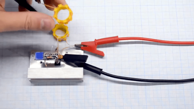
However, in the video, air-core coils go through several orientations to see which configuration has the most and least interference. Using a ferrite core showed similar results. The final examples use toroids and shielded inductors.
One reason ferrite toroids are popular in radio designs is that coils made this way are largely self-shielding. This makes placement easier and means you don’t need metal “cans” to shield the inductors. How much do they shield? The orientation makes a little difference, but not by much. It is more important to give them a little space between the coils. Shields work, too, but note that they also change the inductance value.
While we like the idea of grabbing a breadboard and a scope to measure things, we want to point out that you can also simulate. If you didn’t understand the title, you probably don’t listen to Propellerheads.


This reminded me of the Heathkit SW717 receiver I built when I was 16. It had a persistent hum no matter how many capacitors I added to the (unregulated) power supply. I sold it cheap to a Polish immigrant a few years later and he fixed it by putting some brass shielding around the power transformer. Apparently Heathkit didn’t know how to layout inductors in their designs either.
Eastern Europe electronicalian are really good! At least the ones I know…
Back in the early 90’s, as part of an interview board, I sat in on an an interview for a production engineer position at a major U.S. car company. The applicant was a middle-aged man, a recent Russian immigrant.
They asked they guy if he had any experience with PLCs, to which answered “No.”
Sensing there was more to the story, I prompted him further. He then went on to describe, in surprising detail for his broken English, the microprocessor, RAM, and I/O cards he had designed and hand-wired, the assembler he wrote, application code he wrote, and the factory use-case for a homebrew PCL he’d created for his previous employer’s factory. This guy was brilliant.
The HR Karen (and others) down-voted him because “…he didn’t have PLC experience, which was a requirement for the position.”
I still wonder where that guy ended up and what he could have accomplished given some resources and half a chance.
Ah, C-Stein that humpbacked bastard! Always wondered how he made out, doesn’t exist in my current timeline. Your company’s problem was they were interviewing a PCL guy for a PLC position and they have a lot of backstabbing backstabbers who go around calling people “Karen”. HR is properly employed (!) only in firing related CYA, they have no role in the hiring process and should not be in the room. The problem is the process and the process is the problem.
In some of the older stereos, where the space was at premium, the 120/220 v transformer is rotated something like 30 degrees to offset the inductive coupling. Brass shielding helps, too, and some have these rotated AND shieded.