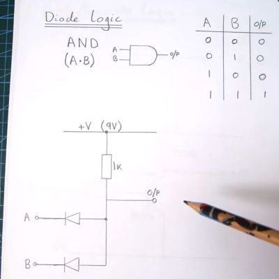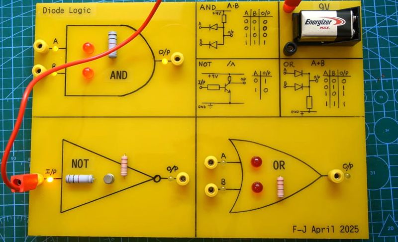
The fun part about logic gates is that there are so many ways to make them, with each approach having its own advantages and disadvantages. Although these days transistor-transistor logic (TTL) is the most common, diode-transistor logic (DTL) once was a regular sight, as well as diode-resistor logic (DRL). These logic gates are the topic of a recent video by [Anthony Francis-Jones], covering a range of logic gates implemented using mostly diodes and resistors.
Of note is that there’s another class of logic gates: this uses resistors and transistors (RTL) and preceded DTL. While DRL can be used to implement AND and OR logic gates, some types of logic gates (e.g. NOT) require an active (transistor) element, which is where DTL comes into play.
In addition to the construction of a rather nifty demonstration system and explanation of individual logic gates, [Anthony] also shows off a range of DTL cards used in the Bendix G-15 and various DEC systems. Over time TTL would come to dominate as this didn’t have the diode voltage drop and other issues that prevented significant scaling. Although the rise of VLSI has rendered DRL and DTL firmly obsolete, they still make for a fascinating teaching moment and remind us of the effort over the decades to make the computing device on which you’re reading this possible.


A rather demonstration system?
Rather advanced, enemic, ingenious?
Also what is VLSI
You did well with defining the others..
VLSI is very large scale integration.
Back when all the circuitry was individual components (like here) those new fangled chip makers would put those components into a single IC, eg the early 74xx or 4000 series. This was SSI “small scale integration”
Then later in the series (all the 3-digit ones and some of the higher 2-digit chips) were released, things like counters and latches and buffers. Those were built from SSI circuits but multiple chips worth now combined into one chip. This is MSI (medium scale integration)
Later many of those multiple MSI chips were combined further into LSI (large scale integration) and here the first CPUs in a single IC package came to be.
But memory manager chips, RAM chips, ROM chips, and others are also LSI.
So take all those things needed to make not just a CPU but a whole computer, combine them all into one chip, and you get VLSI.
Current day Intel and AMD processors fall into this level, where the IC pins take the place of expansion bus slots and to add more memory. Though consumer processors are not technically stand alone, that is almost entirely because integrating RAM would be far too limiting, or at least integrated RAM with no option for external memory.
You can have that too of course but we tend to call them things like SOC (system on a chip) readily available for a smaller market.
Since VLSI has all the things built in we would consider separate SSI/MSI chips of the past, as well as the glue logic internal, you don’t need to use TTL externally to connect those multiple chips together.
So at least for current cutting edge tech, everything comes “glued together” internally, so TTL that glues MSI chips together isn’t needed, and why in that scope TTL is now obsolete.
Another interesting drive from LSI to VLSI was not only size, but speed. Hooking up multiple LSI chips is not the same as a VLSI chip, because the connections between gates in a VLSI chip are extremely short and do not generally need to handle powering a random number of connected devices with random noise issues.
Once you send a signal off-chip, you have to allow for some reasonable amount of load and noise. Thus, a VLSI chip can be internally fast, but the equivalent LSI version would be comparatively slow.
The engineers of old did try to make LSI computers faster by using crazy tech like ECL, but In the end VLSI won.
This is wonderful. 🙂🩶
I just like to remind that tube logic and relay logic used to exist, too.
Especially relays are nice, because they can physically open/close circuits.
And work with different voltages, including high voltages.
Opto-couplers are also interesting since they’re based on diodes/transistors.
There’s so much to experiment. Just try it! 🙂
Not if you invert your logic after the gate. After all, who says “1” must be “true”.
You’d still have issues when combining that with other logic and expanding into larger chains of logic because you’d still need a NOT gate in between two sets that are at two different logic configurations.
Yes, but you still don’t absolutely always need active elements for a NOT gate.
I think it might also be possible if you construct some of the logic using negative voltages.