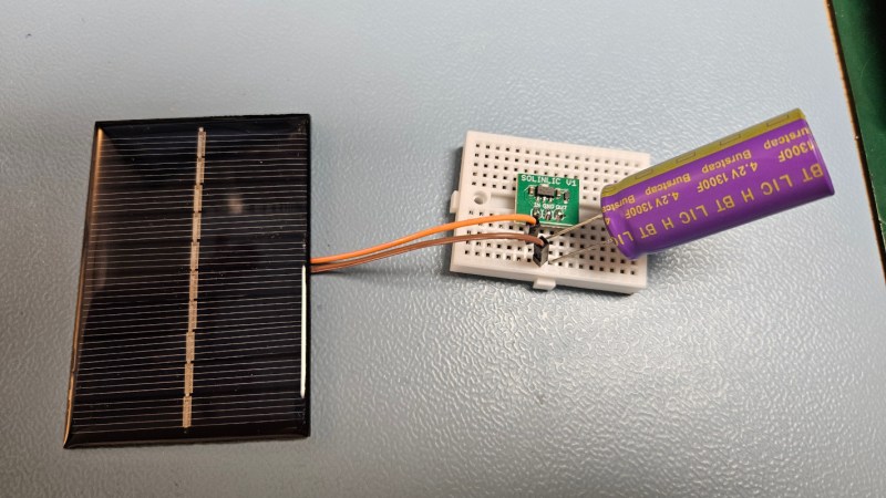
For as versatile and inexpensive as switch-mode power supplies are at all kinds of different tasks, they’re not always the ideal choice for every DC-DC circuit. Although they can do almost any job in this arena, they tend to have high parts counts, higher complexity, and higher cost than some alternatives. [Jasper] set out to test some alternative linear chargers called low dropout regulators (LDOs) for small-scale charging of lithium ion capacitors against those more traditional switch-mode options.
The application here is specifically very small solar cells in outdoor applications, which are charging lithium ion capacitors instead of batteries. These capacitors have a number of benefits over batteries including a higher number of discharge-recharge cycles and a greater tolerance of temperature extremes, so they can be better off in outdoor installations like these. [Jasper]’s findings with using these generally hold that it’s a better value to install a slightly larger solar cell and use the LDO regulator rather than using a smaller cell and a more expensive switch-mode regulator. The key, though, is to size the LDO so that the voltage of the input is very close to the voltage of the output, which will minimize losses.
With unlimited time or money, good design can become less of an issue. In this case, however, saving a few percentage points in efficiency may not be worth the added cost and complexity of a slightly more efficient circuit, especially if the application will be scaled up for mass production. If switched mode really is required for some specific application, though, be sure to design one that’s not terribly noisy.


This looks nice and I have a few questions: Most LDO have a current output limit. I Don’t know how an empty supercapacitor can be described/characterized. Would it be safe if one assumes it behaves like a short when fully emptied? How does the LDO handle running into it’s maximum output current in that case?
Yes, I’m asking the experts! I’m clueless on this one. Please tell me if this approach is safe for my hardware if I should rebuild it. Explanations welcome if you have a minute extra.
The output current of a solar cell is limited by illumination. Size the LDO to handle more than the solar panel’s short-circuit current and you’re fine.
Mind cooling: the LDO might be rated to some maximum, but it comes with caveats like having enough copper area on the board under the ground tab to act as a heatsink, or filled vias to the other side of the board where you can dissipate the heat.
The same applies to transistors. A D-pak casing might be able to handle 28 Watts switching losses, but not as such. If the heat can’t get out, it will fry at much lower loads. Where such things are used, the circuit board might actually be a thick milled copper plate with insulator on top, and the signal traces over the insulator. The transistor sits on top of an “island” milled to the copper plate that pokes through the insulator.
Solar cells basically act as a constant current source. The load from the capacitor will drag down the voltage of the solar panel to the capacitor voltage + the dropout voltage of the LDO. As long as the current rating of the LDO is higher than the short circuit current of the solar panel, it shouldn’t be an issue.
If you want to charge from something other than a small solar panel, you will need a proper battery charging circuit.
That explain how to charge the capacitor, not how to limit the voltage of the capacitor to stay within expected range. A 5V solar panel can output more than 5V when no current is drawn, (like when the capacitor is full), yet your capacitor are limited to 4.2V. Similarly, if you let the system idle on a cloudy day, it’s likely that the capacitor voltage will go below ~2.5V (or so) that would kill your capacitor as well. You need a controller power source that’s able to isolate completely the capacitor in case it’s either full or empty, not something you can do with a LDO. You need to be able to draw switch off the solar panel and switch on the load current from the capacitor when it’s full so its voltage can decrease, and switch off the load and on the solar source when it’s empty so it can resume its operation (with hysteresis). In all cases, you’ll need a switching regulator.
That’s the job of the LDO.
That would be a brown-out condition for your MCU, so it would refuse to start and power up the load.
For example, in one of my devices, there is a power gating circuit that allows current to the MCU every hour, and if the MCU sees less than 2.85 Volts it will refuse to start and the load current will drop to 300 microamps.
This of course means that the battery will keep draining, but at much lower rate, so it should have daysuntil the battery voltage drops below 2.5 Volts. In the mean while, I stop getting communications from the device and my backend script alerts me that the device has dropped out due to running out of battery. The battery also has a low-voltage protection circuit built in at 2.5 Volts while the absolute minimum voltage that the cell will tolerate is 2.0 Volts, so there’s a double failsafe.
Here the solar cell is the limiting factor for current, but what if you want to charge a lithium capacitor from batteries? Suppose for example that your device needs high current for a short while but the battery is something like a lithium thionyl cell that can’t supply it without crashing the voltage down, especially at lower temperatures. Therefore you need a big capacitor.
So you need three things: 1) very low voltage loss, 2) charging current limiting, 3) back-charging current limiting or blocking to prevent accidents when replacing the battery, like a reversed cell or accidentally swapping in an empty cell.
and 3. could be handled with an ideal diode chip, but 2. is more difficult. When you first slot a new battery in, it could draw several amps and the linear regulator could go pop.
The internal resistance of the lithium thionyl cell will limit the current, and if that’s not enough, you can always just place a resistor in series.
I wonder if that can damage the cell. The spec sheets state that high currents at low temperatures result in a loss of capacity.
Or, this could be a regular lithium cell that limits the current when cold, but not when it’s warm.
A similar problem applies to the resistor as well. Suppose you want to charge the capacitor at 500 mA – the resistor will see 2 Watts of heating when the capacitor is empty. For normal capacitors this wouldn’t be an issue because they’re very small, but if you have like 500 Farads of capacitance to charge then it’s going to be a while and a surface mount resistor will get hot enough to desolder itself.
Of course, add more resistors to share the load, but then that’s more parts to lay down.
Or, even if you have normal 1/4 Watt through-hole resistors, you still need eight of them.
It is doable with resistors, but you need to limit the charging current quite low and that means the capacitor can take hours to charge before it can start operating. It also means the device can’t be operating very often or the capacitor doesn’t have enough time to charge back up between uses.
If you’re having to add massive resistors to handle inrush current, it’s not likely your overall design is going to be all that efficient designed around an LDO. Switchers had better be able to operate into a dead short indefinitely and usually fairly efficiently: their bete noire is conversion efficiency at low loads (like maintenance/trickle charge loads.)
Or if you really want some fun, use a switcher for heavy source/load mismatch, and when your difference is low, then switch to the LDO.
True. Then again the low efficiency only applies while the capacitor is charging for the first time. After that, it will supply the load current and the main battery is just trickle charging it to recover the small voltage loss from each load cycle.
If the average load current is just a couple milliamps, though the instant load might be much higher, then the power loss to the resistors should be negligible.
That could be done easily with an MCU, but the whole thing should ideally be “passive” with the MCU sleeping or in a brown-out condition when the batteries are empty. Can’t have the software crash and burn out the circuit.
The comparison can be made with an op-amp, but then you have to deal with its quiescence current at standby, and the circuit can get complicated with lots of components to fit on a small board.
Thanks for the insightful post! I’ll be sure to check the specs of my solar cell to see if it could damage the LDO if the output draws too much from it. I had considered adding a constant current circuit first but the added complexity probably makes it less efficient. Some people use two LM317(T) in tandem to have constant current and constant voltage. Probably with diminishing returns.
Either way this is a nice subject for me to learn more. Some energy harvesting ICs seem to already include protective logic and circuits, but they are too proprietary to understand what they do inside.
A constant current diode might be an answer – it’s very simple – but it’s somewhat limited because it needs a lot of forward voltage to conduct.
You might use one to “soft-start” the capacitor, but as the voltage difference to the source gets less, the diode starts to limit the current even further. At lower forward voltages, it starts to act linearly like a resistor.
In the end, you have to think about what sort of efficiency you’re after. Does it really matter if you waste energy you get from the solar panel if solar panels are cheap and you’re not limited by size – and it avoids using $10 extra in special chips, capacitors and inductors in the switching mode circuit?
More to the point, extra circuitry and components add extra quiescence loads. When your device is not operating, you want to be in the low 10s of microamps or nanoamps if possible with power gating timers. A complicated charge management circuit with regulators of any kind starts to eat up current that you wouldn’t need to generate with a simpler circuit, so your efficiency gains can be all too easily negated. Diminishing returns.
BE sure to read the data sheet on those cap’s. Allot of manuf. are branding them as caps. but they have a minimum voltage like a LTO cell.
Exactly and a maximum voltage too. This design is a guaranteed failure of the LiC. LiC have a minimum voltage and a maximum voltage. They have a lower current capacity than EDLC supercapacitor and a lower cycle life (you can’t derate them to boost the cycle life like a EDLC would do). Their only advantage compared to EDLC is their size and low self discharge rate. But, in fact a LTO cell will likely work better here, with a much higher capacity, a similar cycle life count, a larger current capacity, a larger temperature range and a lower self discharge rate (in µA instead of mA) and a lower price.
Regular lithium batteries – good ones – also work all the way down to -20 for modest current demands. I’ve managed to make it work down to -35 C though the battery can’t be empty because the voltage sags quite badly. Still, it’s enough to start up, send a radio message and shut down immediately. The potentially reduced lifespan doesn’t matter when the device is on standby 99.9% of the time, because the battery will basically get charged once a year from the solar cell and remains full until winter, and then discharges slowly until spring.
The thing you have to mind is that you can’t charge it at negative temperatures, so you need a low temperature cut-off in the charging circuit. You need it anyways, because the solar cell gets hot and heats up the box, so you need to stop charging when it gets to +40 C. Some li-ion cells do accept a very slow trickle charge even down to -20 C. The danger is lithium plating on the electrodes, which de-activates the cell, but if you do it slowly enough the ions can intercalate to the electrode just fine. I’ve seen quotes of 0.01C or 20 mA max.
Since the solar panel output voltage is well matched and just above the desired capacitor voltage, best efficiency and simplest approach at these low currents may be to directly connect solar panel to capacitor and then use a parallel zener diode / LED / LDO arrangement to limit the charge voltage by SINKing current above the fully charged voltage. Like going downhill in a car and using brakes to limit speed.
You need a blocking diode to stop the solar cell from draining the capacitor in the dark. That drops the voltage by couple hundred millivolts.