Taking a picture with a single photoresistor is a brain-breaking idea. But go deeper and imagine taking that same picture with the same photoresistor, but without even facing the object. [Jon Bumstead] did exactly that with compressed sensing and a projector. Incredibly, the resulting image is from the perspective of the projector, not the “camera”.
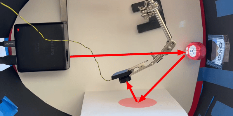
This camera setup is very similar to one we’ve seen before, but far more capable. The only required electronics are a small projector and a single photodiode. The secret sauce in this particular design lies in the pattern projected and the algorithm to parse the data.
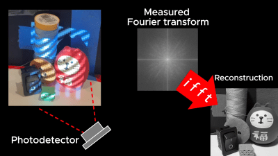
Video is projected onto the target in the form of sinusoidal waves. As these waves change and move their way across the object, the sensor picks up whatever intensity value is reflected. Putting all this data together allows us to create a measured Fourier transform. Use the inverse Fourier transform, and BOOM, you got yourself an image. Better yet, you can even take a picture indirectly. Anything becomes a mirror — even paper — when all you rely on is the average relative intensity of light. If you want to take pictures like this on your own, check out [Jon]’s Instructable.
The science behind this technique is similar to the math that powers CT scanners and VAM 3D printing.
Thanks, [MrSVCD], for the tip!


Ooh, this is exacty what I wanted, except I want this with sound. this could be an imaging sonar…
what happens when you simultaneously record both direct and indirect reflections ? in sonar this is known as the multipath problem. I’m curious if in your setup there is a deterioration or that it does not matter.
Does light not also introduce multipath reflections
And this is why studying math is so important. You never know when you’ll need a paper reflector.
You jest but this is the kind of math that enabled nVidia to verify the authenticity of an image taken on the a moon. The most amazing feats of math are answers to silly questions that happen to have an very powerful applications.
Yeah right, I stopped studying math just far enough to wish for this follow-up video, and it answered all the questions I had. It’s like it was made for me :D thanks !
Godforsaken fscking video with no writeup, so can’t review the content, so sorry if this is covered in it…
Why use a photoresistor when better (faster, more linear) detectors are readily available, especially when using a reconstruction method that requires many samples and demands a linear response from the sensor?
His first attempt was with a photo diode but he had a lot of problems with it. Dynamic range being one of them. The others may be due to his lack of experience with electronics.
Then he switched to a photo resistor and it just worked.
This is how everything worked back in the days of wire photo scanners and Kinoscopes. If you want dynamic range use a photomultiplier tube.
I did something like this in art school in the 80s by scanning a room with a helium neon laser in a pattern that repeated 60 times a second. Put the output of a photomultiplier tube into a video input of a monitor and you have an image.
Echoing what Paul said and to make sure others who want to try this don’t fall into the CdS trap: A CdS (Cadmium Sulfide) Photo Resistor cell can have a long on to off latency. From wikipedea.org: “The lag time when going from lit to dark environments is even greater, often as long as one second.”. It appears [Jon Bumstead] was using CdS photo resistors in the video. It also appears the scanning processes was slow. Perhaps to accommodate the slower CdS photo resistors. Regardless, perhaps a sharper “scanned” image may result if a photo diode light detector was used instead.
The bits about how the image is recorded as if the projector were the camera and the photodiode a light source made me realize that the same must have been true of the very first video camera, the Flying Spot.
The Televisor was the electromechanical predecessor to television, and instead of scanning an electron beam over the phosphor coating inside of a cathode tube, it produced an image by varying the illumination of a lamp behind a spinning disc through which a spiral of holes had been punched. Each horizontal line of the resulting image had its own hole, and by timing the light very carefully and blocking off the view of most of the disc, you essentially had the holes passing through your viewing area left-to-right top-to-bottom, like a raster scan. It sucked. The discs of both the transmitting camera and receiving Televisor had to be absolutely synchronized in order for the picture to be intelligible at all. Also, instead of 480 interlaced lines, the Televisor generally had between 32 and 64 depending on the standard.
BUT! The camera system was ingenious. The Flying Spot used the same disc as the televisor, with a steady lamp behind it. When the light was turned on, only a small part of the scene was illuminated at any one time. The same raster scan would sequentially illuminate different parts of the scene, and the light reflected from it would be picked up by a photoreceptor before being amplified and transmitted.
Even many decades later it was still used, but with a CRT projector. https://en.m.wikipedia.org/wiki/Vitascan
P.S. please do something about remembering username and email, whether I’m using Firefox or Brave, it doesn’t save them.
Hi, reminds me of the Nipkow disk. The televisor must have been the matching monitor, I guess.
In early days of slow scan television (SSTV, 60s), the flying spot scanner was popular, too.
Amazing stuff, love this :-)
Ok here one evil aplication in an incoming cyberpunk world: police and bad guys use a flashlight with a screen included to project sinusoidal waves inside your car, your house or any window so they know what is inside, or simple add it to any single street camera of the city.
I’m sire if they can shine a light in, they can just use a camera directly instead, and be more discreet that flashing alternating patterns around the place….
but the point of course is to see the corners and places that can’t be seen :) so you only need a window to see the entire room even spots you cannot see directly. Something like that guns that can shoot on corners but for light.
Only the camera can be around the corner, the projector still needs to hit the walls directly. So it’s of limited use for this.
But if the TV is your projector, or even an ir led within your new phone charger. There are absolutely dystopian possibilities with this.
This is funny, at a point in time that everybody wears spy devices on his person, including multiple cameras and bluetooth and wifi and cellradios (and microwave band locators and depthsensing) and at a time when TV’s and their remotes spy on you, and both might very well have microphones and cameras depending on the model, you are worried a grainy image might be obtained through pattern projection, which would be the thing that is ‘dystopian’. OK then
Oh did I mention the spooks can now access your phone from freaking space? But nah that is all not something that is a worry.
FT
FFT
FFFT(?)
FT – Forier transform
FFT – fast Forier transform
IFFT – inverse fast Fourier transform
Amazing video with great explanations and short run time.
ok , please make a photo Moon. Sun is the projector, moon is object.
I really want to see the DLP mirror array you plan to use for that.
This is some nice astrophysicist-level work! FT is pure magic.. Adding color seems almost trivial now, just scan three times and stitch together?
If the [jon] read this: what you could try next is recording the light variations and playing them back and see if you can get the same image that way.
Because in the end the sensor just get intensity variations, it’s a simple device and relatively slow since you used a photoresistor, so that means theoretically you can record and re-transmit it I would think. But the proof is in the pudding.