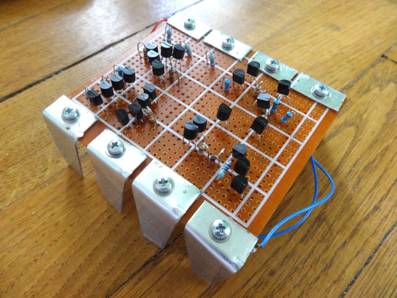
Few electronic ICs can claim to be as famous as the 555 timer. Maybe part of the reason is that the IC doesn’t have a specific function. It has a lot of building blocks that you can use to create timers and many other kinds of circuits. Now [Stoppi] has decided to make a 555 out of discrete components. The resulting IC, as you can see in the video below, won’t win any prizes for diminutive size. But it is fun to see all the circuitry laid bare at the macro level.
The reality is that the chip doesn’t have much inside. There’s a transistor to discharge the external capacitor, a current source, two comparators, and an RS flip flop. All the hundreds of circuits you can build with those rely on how they are wired together along with a few external components.
Even on [stoppi]’s page, you can find how to wire the device to be monostable, stable, or generate tones. You can also find circuits to do several time delays. A versatile chip now blown up as big as you are likely to ever need it.
Practical? Probably not, unless you need a 555 with some kind of custom modification. But for understanding the 555, there’s not much like it.
We’ve seen macro 555s before. It is amazing how many things you can do with a 555. Seriously.


All those transistors? Could have used a ‘555!
… on an FPGA! :-)
The comment I was looking forward to 😛
Now this is true art! 💙
Now build 555 out of vacuum tubes 😉
Has been done, has been documented here.
Evil Mad Scientist has had a kit like this for years. https://shop.evilmadscientist.com/productsmenu/652
Very nice. And I love that there’s an “SMD” version with SMD components 😂
I have one of these hanging on my wall, but it’s doing nothing; I need someone to sell an LED, some 1/4W 5% resistors, and capacitor so I can dead-bug a blinky circuit.
Digital chips are composed of analog elements.
Digital chips are created with CMOS elements that are far more likely to be on, off, or occasionally High Z. Digital elements are designed to operate at those specific values. You might want to take a class or something
Nope. Steve is right.
Digital chips and circuits do not exist. it’s all analog circuits that work with analog levels. The only digital is that when these analog signals pass a certain threshold, they are interpreted as digital data that is either a 0 or a 1.
You may find this pedantic, but it is quite important. For example when translating between different “digital logic families”, decoupling capacitors, cross talk and other signal integrity issues.
It’s also very clear when working with for example I2C. Using a logic analyzer on I2C is quite silly without first verifying with an oscilloscope that the pullups are strong enough and signal integrity is OK.
Many years ago I failed an interview because of that topic. I was asked if I was more of a digital designer or analog designer. I stated, what’s the difference? All digital circuits deep down are analog circuits designed in a “saturation” zone to create a digital state of on/off. You have to understand all the analog side effects to make the design robust.
They didn’t like that answer apparently.
Your reply is spot on. I’ve always said that digital circuits are just analog components behaving badly.
I took such a class. Although it was some time ago, CMOS transistors were pretty old hat.
The class involved a lot of analysis of the analog characteristics of the components, and the factors that tended to optimize their “digital-ness”. Like, how to optimize the noise margins, how to optimize rise and fall times, and so on
In any case all of the analysis was certainly focused on optimizing digital characteristics .. and, probably more importantly, understanding tradeoffs .. e.g. the wider the noise margins, the further an input signal needs to swing, and the more time that takes
But these components operate in the real world .. and so all of that analysis basically involved close examination of the “analog” characteristics of the components.
As far as taking classes. Sure! everyone should take classes. The more of them you take, the richer the understanding of the underlying topics .
Now replace the transistors with triode tubes.
The 741 equivalent to this conversion already is a reality. ^^
https://hackaday.com/2021/06/19/vacuum-tube-magic-comes-to-the-741/
I want to see a 555 made out only of 555s.
That… would tear a hole in the fabric of the universe!
Creating a Mobius…
A twist in the fabric of space, where time becomes a loop….becomes a loop…
.ᵇᵉᶜᵒᵐᵉˢ ᵃ ˡᵒᵒᵖ….ᵇᵉᶜᵒᵐᵉˢ ᵃ ˡᵒᵒᵖ…..
And associated with Evil Mad Scientist, a discrete 6502:
https://monster6502.com/
I saw it at a Maker Faire, and made its makers tired with my stupid questions…
I think I’ve seen a PIC programmed to emulate a 555.
A fully modular 555, the sheer number of uses and modifications possible is infinite!
IMHO, the best update to the venerable 555 was 558/559, ie, quad 555 on one chip. I am kinda surprised that they stopped at that, as I would expect to see hex 555, octo 555, etc. Though, Octo/eght maybe about the top, but still cool. Why so many on one die? Because they’d have exact same specs per.
That or adding equally venerable MOSFETs, though, I suspect there may already be some obscure 555 with FETs built in.
(nobody mentioned arduino … yet … here it is … : – ] ).
You’re very clever, young whippersnapper. Very clever. But we know it’s 555s all the way down!