Designing a circuit is a lot easier on paper, where components have well-defined values, or lacking that, at least well-defined tolerances. Unfortunately, even keeping percentage tolerances in mind isn’t always enough to make sure that circuits work correctly in the real world, as [Tahmid] demonstrates by diagnosing a buck converter with an oddly strong voltage ripple in the output.
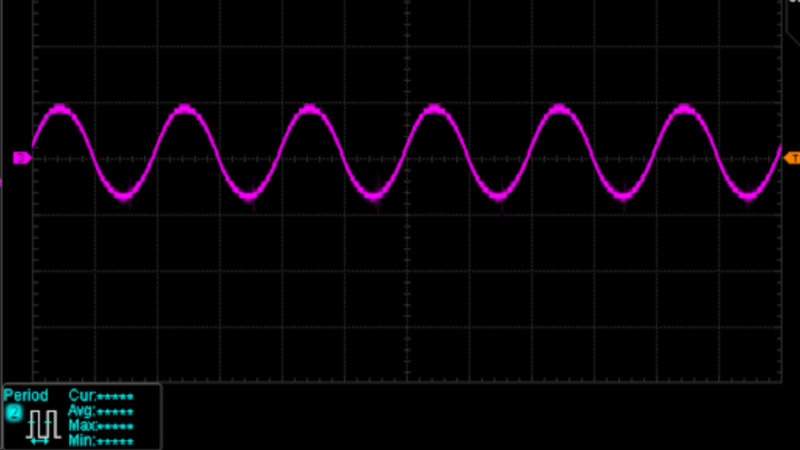
Some voltage ripple is an inherent feature of the buck converter design, but it’s inversely proportional to output capacitance, so most designs include a few smoothing capacitors on the output side. However, at 10 V and a 50% duty cycle, [Tahmit]’s converter had a ripple of 0.75 V, significantly above the predicted variation of 0.45 V. The discrepancy was even greater at 20 V.
The culprit was the effect of higher voltages on the ceramic smoothing capacitors: as the voltage increases, the dielectric barrier in the capacitors becomes less permittive, reducing their capacitance. Fortunately, unlike in the case of electrolytic capacitors, the degradation of ceramic capacitors performance with increasing voltage is usually described in specification sheets, and doesn’t have to be manually measured. After finding the reduced capacitance of his capacitors at 10 V, [Tahmid] calculated a new voltage ripple that was only 14.5% off from the true value.
Anyone who’s had much experience with electronics will have already learned that passive components – particularly capacitors – aren’t as simple as the diagrams make them seem. On the bright side, they are constantly improving.
Coping With Disappearing Capacitance In A Buck Converter


Class 2 ceramic capacitors are probably the most popular way to start learning about Standard Datasheet Lies, the nice-sounding specs that are technically not quite lies but are applicable to approximately 0% of real-world use cases. Like the “75 A” surface-mount MOSFETs that can only handle 15 A unless soldered to a copper brick immersed in ice water, or the “85°C” electrolytic caps that have a lifespan of a few days anywhere near that temperature.
It was way worse before companies started to have easy to browse simulation results (like Murata’s SimSurfing). Now it’s a rite of passage but you’re not tearing your hair out.
Lies, damned lies, and product specifications. “Rated for 2000 Watts… [under breath] for approximately two milliseconds, at which point it becomes a rapidly-expanding cloud of incandescent vapor.”
“No root mean square figures, sorry.”
That’s why you don’t read the “Features” part of datasheet. You check SOA chart for transistors. And yes, it can handle 75A, at 10us pulse width. And learn about thermal characteristics, and how to read them first.
Also when it comes to capacitors, unless your design is under control of accountants, double or triple all filter capacitors in capacity. Also SMD MLCC capacitors are fragile and can crack. Also for any converter, you can’t go wrong with Pi LC filter.
Datasheets don’t lie, they are designed to advertise the product fist, then they include all necessary information. For example a uC datasheet might tell you “High performance” followed by “Low power”, and it’s a perfectly true pair of statements. But you need to get to DC characteristics table to figure out it’s either high performance or low power. And then calculate, if it’s better to run program at low clock for longer, or run it ASAP and then go to ultra low power sleep mode. Turns out, paradoxically that second option might be more efficient…
“unless your design is under control of accountants” – not really true
There are designs, where size matters – and than it gets hard. If you simply don’t have space for large heat sinks or “lets triple all the caps” than it starts to get interesting and you need to get creative.
‘If this was easy, you’d all get liberal arts starting salaries.’
Prof in Engineering school.
Truer words were never spoken.
Your 75A for 10µs figure is a bit outdated now I’m afraid. That was with bond wires; now with copper clip-attach leadframes, they’re cranking 300A+ through those eensy little DFNs. 8-)
Power dissipation is the rule, regardless — whatever the headline might say, under whatever conditions it applies to, if you can’t get the heat out of your application (or you can’t afford to dissipate it in the first place!), it ain’t gonna cut it.
I suppose, it’s not so much a “gotcha” for newbies, but an introduction to nuance. Most engineering applications can safely ignore a couple bulk headline parameters, like the suggested current rating, or maximum power dissipation. And, there are more things at stake than just Rds(on); Qg(tot) and Coss are quite important. Externalities to the circuit, like mechanical construction, thermal performance, are on the table, too.
For example, I have a 12V 80A power supply design, which uses triple 3x3mm DFNs for the synch rectifier (or two 5x6mm “PDSO-8” DFNs, give or take availability and mechanical constraints). They’re rated a meager 80A, but run at ~27A average to keep heat down to a few watts. Gate drive is important here: a larger transistor dissipates more in the driver, as does higher supply voltage (6-9V seems ideal for most parts of this class; 12V is tolerable, but more simply wastes so much power). If I cranked up MOSFET size too far (probably 2-4x where it’s at now), eventually gate drive (and Coss switching loss, even in the resonant application) costs more.
Engineering, at its fullest, is a multidisciplinary optimization problem.
And I wouldn’t have it any other way!
Almost every circuit design I see has something in it I can’t justify with a datasheet reference. I’m usually a by the book designer and it drives me nuts, I have no idea how I’m supposed to review or evaluate it, since it was all done with intuition and testing.
Usually I just tell the truth and say “I have no idea what I’m looking at, the datasheet doesn’t guarantee this, can we like, do this other thing instead so we can reason about it?”
It’s a serious problem for EE’s. MLCC voltage-coefficient of capacitance, and aging give you much much less capacitance than you expect. It varies amongst different manufacturers. Some dielectrics age badly within the first 48 hrs!
Continental Automotive parts maker had big problems with this causing a TI LDO to oscillate. Not sure if it was a safety system like ABS. They lobbied the capacitor industry to add aging data and you’ll now see it in some datasheets. They also train their EE’s on how to select and rate MLCC’s. See PCNS 2019:
https://passive-components.eu/wp-content/uploads/2019/10/HIGH-CV-MLCC-DCAC-BIAS-AGEING-CAPACITANCE-LOSS-EXPLAINED.pdf
You should see it in most aecq qualified parts the thing might be on giggidy key or whatnot is you only see the datasheet common to the family of parts … only when you are in the market for millions of units for automotive or above then you start seeing different sheets
I had that issue last year with a ti chip the public datasheet didn’t cover what the engineer was setting things up. Once I talked with our rep a new confidental datasheet showed up and it was twice as many pages
Confidential datasheets make me angry. We’re already buying your part, ffs, tell us how to use it!
I have a few BMS modules from laptop batteries. I can’t use them because TI requires NDA. Of course I can buy (a bit expensive) software to reprogram them from third party that has a NDA with TI. I don’t really see the point. It won’t keep dishonest sellers from reprogramming batteries to show more capacity than they have. And if the user wants to mess with the battery, then it’s their fireball to deal with…
The other option seems to be companies no longer releasing parts to the public. They’re limited distribution parts and also datasheets.
It’s really hard to provide applications support to newer, more complex power converters, especially to the general public/small companies.
Noobie here. This is good to know.
I thought this was only an issue with dodgy Chinese clones. I got bit once with buck converter modules, twice with LiPo batteries, and now I have a synthetic load tester. For me, the takeaway is over engineer and test test test.
In researching my own issue with related problem, I discovered by actual measurements that for same capacitance, same voltage rating, the bigger they are the less affected by DC voltage they are.. That is don’t use an 0805 when a 1206 will fit !
Also choose fatest (height) you can afford even for same footprint.
Phil
There is much more to that. It also greatly depends on the actual ceramic uses for the capacitors. to get some idea, look up things like: X7R, X5R, C0G
The main culprit is ceramic type, but size actually matters more than I thought!
look here, from kelly’s reply:
PCNS 2019:
https://passive-components.eu/wp-content/uploads/2019/10/HIGH-CV-MLCC-DCAC-BIAS-AGEING-CAPACITANCE-LOSS-EXPLAINED.pdf
Another trick is to include a capacitor that has a self resonate frequency close to that of the switching supply. You want to place this one as close to the switched output and ground as possible.
Of course it’s not necessarily the case that they pack the maximum electrode count into a chip of a given size and voltage rating, but a too-small chip definitely, physically, can’t [offer the C(V) at all].
At least from what I’ve seen of major brands in the western market, they do indeed compete for C(V) in size — but I will be careful to note, that impression is specifically filtered by my insistence on buying only parts with a char sheet. No char, no sale!
I don’t pick anything worse than X7R as a rule; X5R is tolerable in commercial applications.
Incidentally, C0G is not only free of C(V) dependency, but also tempco, and loss, pretty much. C0G capacitors are about as close to an ideal capacitor that you’ll ever touch. And I mean this quite seriously: vacuum capacitors are quite rare items — and frankly not that much better(!); and superconducting capacitors or resonators arguably cannot be physically touched, as your skin is instantly turned to very brittle ice on contact..! (In the sense of, what “you”ness is touching it anymore, etc..) C0G are so low loss, they can’t really be connected in parallel, per se: in one application, I had a row of 10nF 630V 1210s on a board, side by side, joined by polygon pours, over ground plane. The ~5nH between each capacitor made a lumped-equivalent transmission line with a lowest self-resonant frequency around 12MHz. The Q was low (~8?) but definitely visible in the EMI spectrum (it was a power supply).
Which is another random insight that you don’t see / appreciate very often: in a sense, resistance is responsible for capacitors acting in parallel, or inductors in series. Without which, stray inductance and capacitance of the physical arrangement itself (no component is zero dimension, or the speed of light, infinite) guarantees various wacky LC behavior, peaks and valleys all over the place, circuits ringing like a steel plate; it’s the damping of resistance that makes all these resonant modes sit down and the components behave in the expected low-frequency manner!
At the moment Ti seems to be playing a dirty trick. They’ve turned the good old TL074 from a Jfet process to a (cheaper) CMOS process, and at the same time this lower power consumption, but the noise is doubled.
https://www.eevblog.com/forum/beginners/what-tl074s-are-still-jfet/
It’s a very common pitfall for newbies, with predictable (that is, once you know how they behave!) results. I’ve been compiling a list on Stack:
https://electronics.stackexchange.com/questions/713381/correct-placement-of-series-ferrite-beads-to-avoid-dc-disconnect-during-power-cy/713473#713473
The exact title of this question is a bit irrelevant; the usual suspect (stray wiring inductance) suffices to explain the problem. Answer includes a simple nonlinear simulation demonstrating inrush overshoot, and two solutions.
It’s nice that it’s predictable and many vendors often provide technical documentation that documents this variance. I have found the Murata and TDK sites to be easy to use and find the right info. However, there seems to be variance between vendors and when using a part that doesn’t have the bias documented, the safe bet is to find a comparable physical cap and then derate, derate, derate to overdesign.
It might help if they measure the capacitor before putting it in the circuit, i’ve had many capacitors say x-uF and test outside its % tolerance.
A tricky thing here is that the capacitance will vary with bias voltage. So even if you measure it ahead of time, unless you can guarantee that the measurement device is going to bias it at the same voltage as your application (unlikely), the real in-circuit capacitance will be even lower than measured.