Do you or a loved one suffer from distorted 3D prints? Does your laser cutter produce parallelograms instead of rectangles? If so, you might be suffering from CNC skew miscalibration, and you could be entitled to significant compensation for your pain and suffering. Or, in the reality-based world, you could simply fix the problem yourself with this machine-vision skew correction system and get back to work.
If you want to put [Marius Wachtler]’s solution to work for you, it’s probably best to review his earlier work on pressure-advance correction. The tool-mounted endoscopic camera he used in that project is key to this one, but rather than monitoring a test print for optimum pressure settings, he’s using it to detect minor differences in the X-Y feed rates, which can turn what’s supposed to be a 90-degree angle into something else.
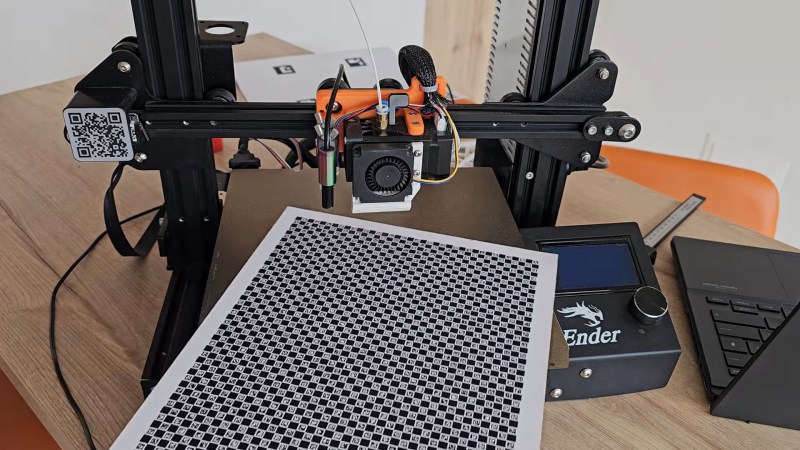
The key to detecting these problems is the so-called ChArUco board, which is a hybrid of a standard chess board pattern with ArUco markers added to the white squares. ArUco markers are a little like 2D barcodes in that they encode an identifier in an array of black and white pixels. [Marius] provides a PDF of a ChArUco that can be printed and pasted to a board, along with a skew correction program that analyzes the ChArUco pattern and produces Klipper commands to adjust for any skew detected in the X-Y plane. The video below goes over the basics.
For as clever and useful as ChArUco patterns seem to be, we’re surprised we haven’t seen them used for more than this CNC toolpath visualization project (although we do see the occasional appearance of ArUco). We wonder what other applications there might be for these boards. OpenCV supports it, so let us know what you come up with.


ChAruco boards are standard for calibrating the distortion of a camera. Very important when trying to get the camera position relative to some marker, like an Apriltag (used in robotics and drone navigation). For instance, https://mrcal.secretsauce.net/
Why do 3d printing people keep making software corrections for their machine being out of square?
Because getting a frame square is often harder than it looks. Even measuring how far out is it can be challenging. You should try it one day. See also backlash, drunken threads, belt bouncing etc etc.
The real question is why they keep re-inventing the software when it’s been a feature of CNC for decades. And if it’s not in your system, that’s why G-code per-processors exist.
Printers are tiny. Just loosen the bolts and hold a square to the frame when you re-tighten them, then print some cubes and mic em to be sure. I’ve done this with every printer I’ve owned; I’m not sure why you’re pretending it’s hard.
Why do machinists keep putting hundreds of kilograms of metal in their machines? You say that like software is a bad thing, whereas I say having to pay for lots of metal that just sits there making my printer too heavy to put in my house is a bad thing.
There’s multiple ways to get a desired behaviour, and none are optimal – they all have their tradeoffs.
Tramming a printer doesn’t require any extra material. Just some time, a machinist’s square, and (worst case) some shims.
Most 3D printing people don’t build their own printers and live with whatever comes from the factory. Those who do build printers are generally of two camps. 99% try to duplicate commercial stuff with crappy beds and autotramming because they saw a youtube video of a printer tramming itself and thought it was cool without understanding why it is necessary. About 1% build them more like machine tools with flat beds on kinematic mounts and with square axes that don’t require all the firmware tweaks to get them to print accurately, precisely, and reliably.
Oh well. It’s OK. Most 3D printing people mainly print starwars junk and tugboats that get thrown in the trash 10 minutes after printing. How good a printer do you need for that? When they tire of it, or it breaks and they have no idea how to fix it, their printer will end up at the next garage sale.
I’ve never built my own printer from scratch, though. I just make sure it’s square when I assemble it. You don’t need expensive precision parts because there’s little to no forces involved in 3d printing (if you’re doing it right), and your tolerances are limited to ~0.1mm by the fact that plastic shrinks unpredictably anyways.
I swear, this isn’t black magic! Just put the legos together correctly!
That’s how we got at cheap 3D printing for everyone. Machines got stripped down to bare essentials, and everything else is software correcting for hardware shortcomings. Everything in the slicer to firmware motion planner is tuned to account for hardware limitations. This is not really any different.
Because it is extremely hard to build one perfectly squared. Good luck with you 3000eur granit slob and hundreds of euros of machnist squares squaring misumi beams because LDO ones are just not straight (and those are the priemium ones) only to have it all goes to WASTE because of giving plastic parts and unmeasurably small difference in belt tensions.
FFS even those expensive Bambu printers uses optical skew calibration for these reasons!!
Perfection is impossible to achieve in the machine shop.
If you attempt to achieve perfection, you will achieve bankruptcy.
Aluminum extrusions are far from straight and square.
You can surface grind all six faces and it will still be ‘far’ from straight and square.
Aluminum bad material choice for home made precision straight edge.
Punchline:
Math major: I’ll never get to the girl.
Engineering major: I’ll get close enough!
Aluminum extrusions are ‘straight enough’ for machines that work by spitting about 0.2 mm streams of plastic snot and generate little force.
Their ends can be cut ‘square enough’, if the manufacturer cares to.
Doesn’t need to be perfect (no such thing), just needs to be within 0.x mm (you decide) across the width of the bed. Not difficult to achieve, even with a harbor freight square. I’m convinced you guys are just too scared/lazy to use hand tools.
Useless. Just build your printer correctly.
Even those expensive premium factory-made Bambu printers made with full metal gantry and frame use the same optical calibration method. Because at those dimensions even a slight difference in belt tension or a slight difference in bearings play a role plus those are wearables.
Bambu printers are built like garbage and come with warped beds. They use optical calibration to avoid paying for quality control.
This is a great concept, I can’t wait to see what else comes from this.
And Bob asked why it’s not on your system, skew correction is in klipper but the camera integration in the tool head is generally lacking on a lot of machines, hence the project maker using an endoscope, so this will add a framework to allow this for anyone. Generally skew correction is as described in the video, do a test print, measure some things, do some math, punch the numbers in to klipper/the slicer and you’re done. It just depends on the slicer or firmware that you’re using on the machine.
Honestly, this would be great for a delta printer, those things are hard to calibrate software or hardware.
Good as long as your 2D printer isn’t out of skew.
Printing a mirror image on a transparency film could help check for any errors in the printout.
I had incredible results with the califlower / calilantern.
i’m excited about even baby steps towards closed loop control, and i’m all about using software calibration to correct for hardware defects. and this is just plain a neat way to do it.
but i also just don’t really see it as that big a deal. i’ve had two printers (one of them a delta) and i’ve calibrated them by hand and then tried to quantify the limits of my calibration error, and then tried to extrapolate what kind of error that will produce in my prints. and it’s just tiny. i calibrate to a way higher standard than i need to, for the way i use my printer. and it’s not very hard.
there are people who don’t calibrate their printers at all, who have build plates that still look like tacos from the way the tension distributed itself during shipping. and i just think, they won’t bother to use this sort of calibration any more than they bother to use any other kind of calibration :)