D-POINT: A Digital Pen With Optical-Inertial Tracking

[Jcparkyn] clearly had an interesting topic for their thesis project, and was conscientious enough to write up a chunk of it and release it to the wild. The project in question is a digital pen that uses some neat sensor fusion to combine the inputs from a pen-mounted gyro/accelerometer with data from an optical tracking system provided by an off-the-shelf webcam.

A six degrees of freedom (6DOF) tracking system is achieved as a result, with the pen-mounted hardware tracking orientation and the webcam tracking the 3D position. The pen itself is quite neat, with an ALPS/Alpine HSFPAR003A load sensor measuring the contact pressure transmitted to it from the stylus tip. A Seeed Xaio nRF52840 sense is on duty for Bluetooth and hosting the needed IMU. This handy little module deals with all the details needed for such a high-integration project and even manages the charging of a single 10440 lithium cell via a USB-C connector.

Positional tracking uses Visual Pose Estimation (VPE) assisted with ArUco markers mounted on the end of the 
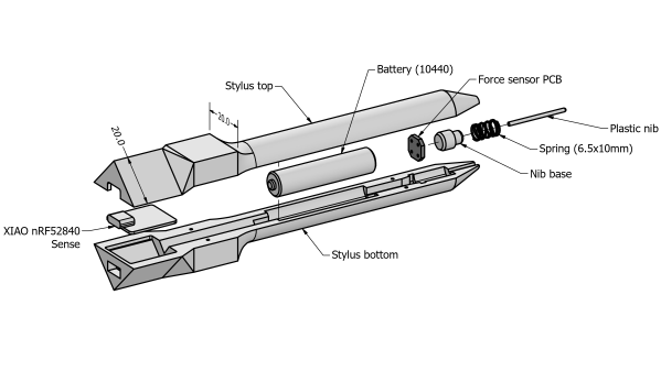
stylus. A consumer-grade (i.e. uncalibrated) webcam is all that is required on the hardware side. The software utilizes the familiar OpenCV stack to unroll the effects of the webcam rolling shutter, followed by Perspective-n-Point (PnP) to estimate the pose from the corrected image stream. Finally, a coordinate space conversion is performed to determine the stylus tip position relative to the drawing surface.

The sensor fusion is taken care of with a Kalman filter, smoothed with the typical Rauch-Tung-Striebel (RTS) algorithm before being passed onto the final application. This process is running in Python using the NumPy module, as you would expect, but accelerated using the Numba JIT compiler.

Motion tracking is not news to us, we’ve seen many an implementation over the years, such as this one. But digital input pens? Why aren’t they more of a thing?

Thanks to [Oliver] for the tip!

Purpose-Built Plotter Pitches In To Solve Wordblitz On Your Phone

It seems like most hackers have never played a game without at least wondering how to cheat at it. It’s not that we’re a dishonest lot, at least not as a rule. It’s more that most games hold less challenge for us than does figuring out how to reverse engineer the game’s mechanics. We don’t intend to cheat; it just sort of happens.

Or at least that’s the charitable way to look at such smartphone game cheats as this automated word-search puzzle solver. The game is Wordblitz, which is basically an implementation of classic Boggle along with extra features to release more dopamine and keep you playing. Not one to fall for that trick, [ghettobastler] whipped up a quick X-Y gantry from MDF using a laser cutter, added a stylus in the form of a cotton swab tipped with aluminum foil, and a vision system based on a simple web camera. The bed of the gantry has a capacitive plate so the stylus can operate the phone, along with a frame of ArUco fiducial marker to aid in locating the phone.

A Raspberry Pi handles the machine vision part of the process, which uses OpenCV to estimate the phone’s location and extract the current game tiles. The words in the game field are located by a solver that [ghetto] had previously written; a script then streams G-code to the plotter to peck out the answers at blazing speed, or at least faster than even [Peggy Hill] could manage. See the video below for a sample game being solved.

One word of warning if you choose to build this: [ghettobastler]’s puzzle-solving algorithm is based on a French dictionary, so you’ll have to re-teach it for other languages. But whatever language it’s in, this reminds us a bit of some of the Wordle solvers we’ve seen recently.

Continue reading “Purpose-Built Plotter Pitches In To Solve Wordblitz On Your Phone”

Someone setting down an arUco tag

Make Your Own Virtual Set

An old adage says out of cheap, fast, and good, choose two. So if you’re like [Philip Moss] and trying to make a comedy series on a limited budget rapidly, you will have to take some shortcuts to have it still be good. One shortcut [Philip] took was to do away with the set and make it all virtual.

If you’ve heard about the production of a certain western-style space cowboy that uses a virtual set, you probably know what [Philip] did. But for those who haven’t been following, the idea is to have a massive LED wall and tracking of where the camera is. By creating a 3d set, you can render that to the LED wall so that the perspective is correct to the camera. While a giant LED wall was a little out of budget for [Philip], good old green screen fabric wasn’t. The idea was to set up a large green screen backdrop, put some props in, get some assets online, and film the different shots needed. The camera keeps track of where in the virtual room it is, so things like calculating perspective are easy. They also had large arUco tags to help unreal know where objects are. You can put a wall right where the actors think there’s a wall or a table exactly where you put a table covered in green cloth.

Initially, the camera was tracked using a Vive tracker and LiveLink though the tracking wasn’t smooth enough while moving to be used outside of static shots. However, this wasn’t a huge setback as they could move the camera, start a new shot, and not have to change the set in Unreal or fiddle with compositing. Later on, they switched to a RealSense camera instead of the Vive and found it much smoother, though it did tend to drift.

The end result called ‘Age of Outrage’, was pretty darn good. Sure, it’s not perfect, but it doesn’t jump out and scream “rendered set!” the way CGI tv shows in the 90’s did. Not too shabby considering the hardware/software used to create it!

Invisible 3D Printed Codes Make Objects Interactive

An interesting research project out of MIT shows that it’s possible to embed machine-readable labels into 3D printed objects using nothing more than an FDM printer and filament that is transparent to IR. The method is being called InfraredTags; by embedding something like a QR code or ArUco markers into an object’s structure, that label can be detected by a camera and interactive possibilities open up.

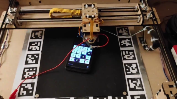
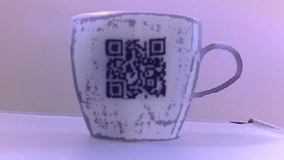
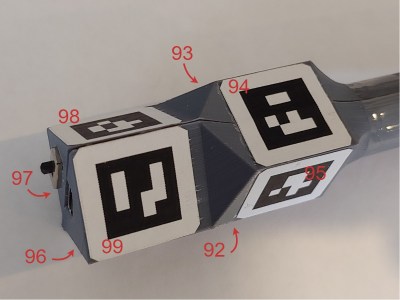
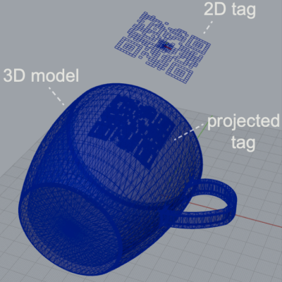
One simple proof of concept is a wireless router with its SSID embedded into the side of the device, and the password embedded into a different code on the bottom to ensure that physical access is required to obtain the password. Mundane objects can have metadata embedded into them, or provide markers for augmented reality functionality, like tracking the object in 3D.

How are the codes actually embedded? The process is straightforward with the right tools. The team used a specialty filament from vendor 3dk.berlin that looks nearly opaque in the visible spectrum, but transmits roughly 45% in IR.  The machine-readable label gets embedded within the walls of a printed object either by using a combination of IR PLA and air gaps to represent the geometry of the code, or by making a multi-material print using IR PLA and regular (non-IR transmitting) PLA. Both provide enough contrast for an IR-sensitive camera to detect the label, although the multi-material version works a little better overall. Sadly, the average mobile phone camera by itself isn’t sufficiently IR-sensitive to passively read these embedded tags, so the research used easily available cameras with no IR-blocking filters, like the Raspberry Pi NoIR.

The PDF has deeper details of the implementation for those of you who want to know more, and you can see a demonstration of a few different applications in the video, embedded below. Determining the provenance of 3D printed objects is a topic of some debate in the industry, and it’s not hard to see how technology like this could be used to covertly identify objects without compromising their appearance.

Continue reading “Invisible 3D Printed Codes Make Objects Interactive”