Ever tear open a potentiometer? If you haven’t, you can still probably guess what’s inside. A streak of resistive material with some kind of contact that moves across it as you rotate the shaft, right? Usually, you’d be right, but [T. K. Hareedran] writes about a different kind of pot: ones that use magnetic sensing.
Why mess with something simple? Simplicity has its price. Traditional units may not be very accurate, can be prone to temperature and contamination effects, and the contact will eventually wear out the resistive strip inside. However, we were a little curious about how a magnetic potentiometer could offer a resistive output. The answer? It doesn’t.
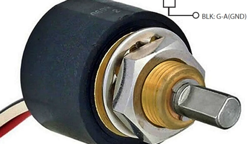
Really, these would be better described as rotary encoders with a voltage output. They aren’t really potentiometers. The SK22B mentioned in the article, for example, requires a 5 V input and outputs somewhere between 10% and 90% of that voltage on the ersatz wiper pin.
That makes the devices much easier to puzzle out. The linearity of a device like that is better than a real pot, and, of course, the life expectancy is greatly increased. On the other hand, we’d rather get one with quadrature or I2C output and read it digitally, but if you need a voltage, these devices are certainly an option.
[T. K.] goes on to show how he fabricated his own non-contact sensor using photosensors and a gray-coded wheel with a single track. You do need to be careful about where you position the sensors, though.
Could you make a real non-contact resistive pot? Seems like you could get close with an FET output stage, but it wouldn’t be as generally applicable as a good old-fashioned smear of carbon. If you have a better idea, drop it in the comments or build it and give us a tip.
Want a 20A-capable device? Build it. Want to see how we like to read encoders?


why not using a digital pot as output stage ? they DO provide resistive output AFAIK
Linearity is often meh.
Magnets are also suseptible to heat but prob at much higher temps than a regular pot I would imagine
they also do pwm, i2c, or spi in some cases. rather keep the analog in the can.
I have wanted something like this for quite some time for my projects where i worry about normal pots wearing out. Its probably an unfounded fear but still…
I wonder if they can make this even easier. There are “magnetoresistive” sensors on the market which are solid state magnetic field sensing devices (or as I have heard many people claim, magnetic field activated MOSFET). I wonder if they can be an even easier and robust solution here, without I2C and an MCU to control the chip
We have applications for motion systems where the pots wear out eventually and I need something like this, but 0-10V instead of 0-5.
it’s not 0-5 even, it has a 5v supply but only returns a voltage between 0.5 and 4.5v, so it’s not a rail to rail voltage. I have buiilt something similar using Allegro A1324 linear hall sensors placed between two neodymium magnets, sensing the rotation of the magnetic field on an arc of appoximately 90 degrees, for use in a joystick. It loses a bit of resolution compared to the original potentiometers because you lose 20% of the decoder range, but it completely gets rid of noisy and drifty pots. But I guess it would be possible to condition the signal through an opamp to recover the top and bottom of the range, and possibly to condition the signal for the 10v rail you need.
use an adc that lets you set voltage references at either end. thus you can maximize your resolution through the desired mechanical range.
There is a valid reason to use magnetbased sliders (pots) in gameconsolea like the switch. Overtime the carbon wears out in them and the zero position drifts. With non-contact solutions this is fixes
For information, digital encoders with mecanical, optic ou magnetic contacts aren’t potentiometers… A potentiometer has a resistive piste and can be used without electronic potentiometer, microcontroler ans encoders….
This is quite a neat application of turning a magnetic quadrature encoder into an analog part. Where for many applications this is more useful than a potentiometer.
I’ve recently found out that my quadrature encoders are also just magnetic encoders in a fancy package. While this is fine for many applications, it didn’t give me the accuracy of a high count old stock quadrature encoder. That may also be the reason why the industrial versions are rather expensive.
Is this stuff actually available? The SK22 is a 25 year-old part.
as5600, as5048, mt6701, to name a few. mid you these are all chips and dont come with the mechanical bits. i dont much like the 5600 because it doesnt let you change the i2c address which makes having multiples troublesome. the 5048 is better, 14 bit vs 12, has spi output. i think all of the above could be configured for pwm output.
These have been the standard for half-decent performance TPS (throttle position sensor) for like.. 20 years?
Not sure I would describe them as a pot since – as the article stated, they aren’t resistive which limits their use to user inputs or – again, position sensing. They do however, provide an output that is relative to its power supply, so, like a voltage divider, doesn’t require any kind of precision reference since an ADC will just measure this fraction if the power supply is used as the reference.
I used one of these to make my own beam heading indicator for my rotating ham radio antenna and it works great. I plan to use a couple more of them as feedback indicators if I ever get around to making my own AZ_EL rotator for satellite tracking.
https://www.amazon.com/Sensor-Resolution-0-088%C2%B00-360-Degrees-Rotatable/dp/B0B5XRRFNN/ref=sr_1_1_sspa?crid=7HIQG1N8X0J&dib=eyJ2IjoiMSJ9.eMO3RaO8DApLLyh92QrG7BU3E51SWHRsf1EVekzwjSm4ARnva80U7pPkxNq97iT65gWHt0rVEykImJFomlEOH-pzLuCITv3urnkMRQmjLyA3ThNapP3U_MgKJ4Q_670hm9KIWgI15bVXR1FUqE0wBKyl3X0NuyUNBDPNorEg2LmI-Sc7bk1SitHVgJ0h_KXGOaRpE30Bizc84_MAU5jp9qh-p7w9RTVS2D2NQ1k9Qtg.0kLw6kD4JXDpKGJzd7jlz9RZ-SxtnAsoYPAlN-Uu0Bg&dib_tag=se&keywords=hall+effect+rotary+sensor&qid=1757186946&sprefix=hall+effect+rotary+sensor%2Caps%2C191&sr=8-1-spons&sp_csd=d2lkZ2V0TmFtZT1zcF9hdGY&psc=1
please clean your links….
https://www.amazon.com/Sensor-Resolution-0-088%C2%B00-360-Degrees-Rotatable/dp/B0B5XRRFNN/
please clean your links….
https://www.amazon.com/Sensor-Resolution-0-088%C2%B00-360-Degrees-Rotatable/dp/B0B5XRRFNN/
I’m sure there’s a way to construct a tubular continuous reed switch with attached resistor “plate”(?) and a rotatable inside – when you turn the magnet the throughput resistance changes.
Maybe not exactly analog but quantized in very tiny steps? (depending on the exact mechanical design).
You’d still have mechanical contacts but they’d be encapsulated in an inert(?)/vacuum(?) environment and not susceptible to dirt and whatnot.
ive been working on this for some time, though im sure commercial drop in components are available. initially i tried single hall sensor, but the clipped ends are troublesome.
contactless potentiometers/encoders are much better and give you better range and more output options (analog, pwm, i2c, spi, etc). i like keeping the signal digital on the way to the mcu and the parts can be magnetically and electrically shielded so as not to interfere with other components.
nobody talks about option 3 which is an optical solution. one of my joystick projects includes an analog trigger using an led and photodiode pair. the trigger has a curved piece with a v-groove in it, which goes between the led and photodiode, and there are slots printed into the frame. it only gives me a couple volts of throw, but its more than enough for an analog trigger. but there is plenty of room for refinement.
The correct answer is switch capacitor resistors.
switched (oops)
LED, photoresistor, and rotating aperture obvs