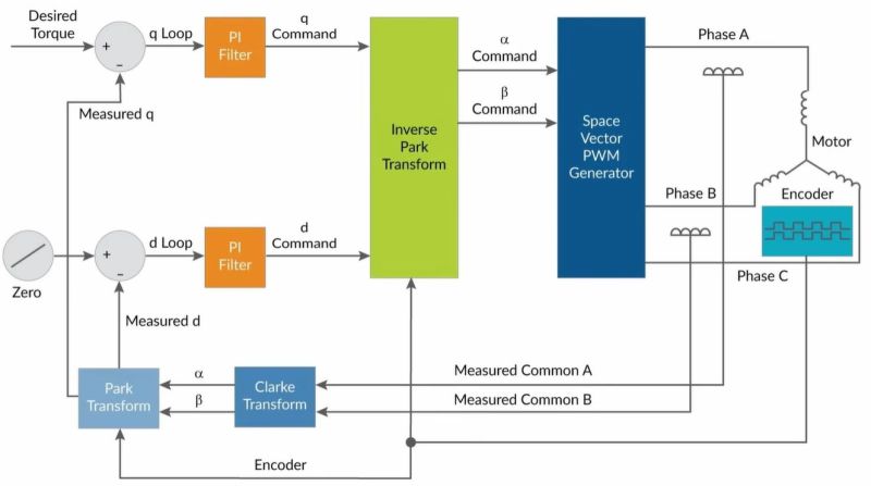
Vector Control, also known as Field Oriented Control or FOC is an AC motor control scheme that enables fine-grained control over a connected motor, through the precise control of its phases. In a recent video [Excessive Overkill] goes through the basics and then the finer details of how FOC works, as well as how to implement it. These controllers generally uses a proportional integral (PI) loop, capable of measuring and integrating the position of the connected motor, thus allowing for precise adjustments of the applied vector.
If this controller looks familiar, it is because we featured it previously in the context of reviving old industrial robotic arms. Whether you are driving the big motors on an industrial robot, or a much smaller permanent magnet AC (PMAC) motor, FOV is very likely the control mechanism that you want to use for the best results. Of note is that most BLDC motors are actually also PMACs with ESC to provide a DC interface.
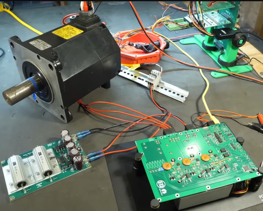
The actual driving is done with two MOSFETs per phase, forming a half-bridge, switching between the two rails to create the requisite PWM signal for each phase. Picking the right type of MOSFET was somewhat hard, especially due to the high switching currents and the high frequency at 25 kHz. The latter was picked to prevent audible noise while driving a robot. Ultimately SiC MOSFETs were picked, specially the GeneSiC G3R30MT12K. Of note here are the four legs, with a fourth Kelvin Source pin added. This is to deal with potential gate drive issues that are explained in the video.
With the hardware in place, whether following the [Excessive Overkill] GitHub projects or not, what makes all of it work is the software. This is where the microcontroller aspect is essential, as it has to do all the heavy lifting of calculating the new optimal vector and thus the current levels per phase. In this controller an STM32F413 is used, which generates the PWM signals to drive the half-bridges, while reading the measurements from the motors with its ADC.
As can be seen in the resulting use of this controller with old industrial robots, the FOC controller works quite well, with quiet and smooth operation. This performance is why we’re likely to see FOC and PMAC motors used in applications like 3D printers in the future, though the rule of ‘good enough’ makes the cost of an FOC controller still a tough upsell over a simple open loop stepper-based system.


Way overcomplicated for tasks where basic microstepping can be done with R-Pi and some Python code. Control engineers are usually creepy and awkward when in presence of a woman.
what a dumb comment
Not at all. The speed and positioning under FOC depends on the error signal derived from the measured motor state, which means you have to accept some error band around the desired path for the control scheme to operate.
This is analogous to the way a stepper motor deviates from the desired position under load, except with a stepper motor you don’t have to compute anything and it’s already built for good precision without active feedback. If the motor is sized incorrectly and cannot perform the required motion with acceptable error, then you can’t help it with FOC because the motor is still too weak or your demands are unrealistic.
The FOC PMAC motor looks good in demos, but you can’t see with the naked eye whether the performance is really superior. What’s likely, you’re spending months of engineering and fine tuning just to arrive at the same point that you’d have with a simple stepper motor. All at the cost of much more complicated control hardware, more software and code, and more things to troubleshoot with the encoders and sensors.
The main deciding question is rather, whether the characteristic torque and power curve of the stepper motor vs. the coarser PMAC motor is better or worse for the application. One control method in itself is not clearly better. Doing FOC for the sake of doing FOC is not a good idea, but nerds are going to nerd about it anyways because it’s complicated and cool.
On the point of torque and power, because the PMAC/BLDC motor is coarser than a stepper motor, it’s going to be a faster motor. For applications where you want direct drive, this is like trying to launch your car in third gear. It can be done, but the performance will suffer until you get up to speed.
For things like 3D printers where you’re constantly slowing down and accelerating from a stop, you will actually spend most of your time going relatively slowly. You’re not extruding at a million miles per hour, and when you are moving rapidly you’re not extruding and not demanding high precision, so the apparent dynamic performance of a BLDC motor is mismatched.
If you gear it down, you face the problem of inertia, because the energy stored in the rotor is proportional to the square of its RPM, so starting and stopping the motor consumes most of your torque.
He does a fairly lengthy discussion of this in the video and describes quite precisely why a FOC is the best option in this application.
Do you have any meaningful input on this, or do you just want to continue talking about other hypothetical scenarios where FOC might not be the best option?
I tried watching the video again, but couldn’t find any such argument. Could you point at a specific time?
Though what I noticed is that his explanation of why a BLDC motor is a PMAC motor was wrong. The conclusion is correct, but the argument is false: the fact that a BLDC motor produces roughly sinusoidal waveforms as a generator has nothing to do with it.
He also confuses maximum efficiency with maximum torque. Efficiency can’t be defined until you count how much power (torque x speed) the motor is actually producing, which is not the same as what power you’re putting in to generate torque.
The applied field is also not always applied in a perpendicular direction: assuming your magnets and stator iron are not yet fully saturated, you can improve torque by applying a field with the magnets, or reduce the field strength by applying a field against the magnets, thus altering the Kv constant of the motor for more torque or more speed.
it was nat that part of the comment I was refering to
“What’s likely, you’re spending months of engineering and fine tuning just to arrive at the same point that you’d have with a simple stepper motor.”
Definitely seems this way from my very limited exposure to the problem in the domain of 3d printers. Obviously, closed loop control, torque control, all sorts of things are valuable and awesome and ultimately i think inescapable. But today, the braindead approach of “send out the pulses and assume the motor moves as commanded” is used by almost every printer out there and it works really well even though there definitely are printers that are miscalibrated / worn out where missing steps can be a huge problem. But people just solve that problem in front of them and then the open-loop control works again.
I think open loop control works good where the forces required are known like in a 3D printer where there is little constant resistance to movement. Closed loop control are superior where there is a variable load like in a CNC mill where an axis can be loaded heavily while another axis is more free to move.
The key to good response from a closed loop servo (no matter which type of motor it is based on) is to have accurate feed-forward settings first. Sometimes servo controls only have PID, but without feed-forward we lose on the instant response that open-loop systems have.
For achieving position control with BLDC motors it can make more sense to control voltage (speed) rather than current (torque). In either case the FOC algorithm is used for optimizing the phase angle. If position is controlled through current, it’s best to have PIDD2 controller (torque is the second derivative of position).
And feed-forward is about having a more or less accurate model of your system to predict how it’s going to behave when you apply control inputs. It does not of course predict external disturbances like the introduction of a load unless you have some sort of sensors to detect that in advance.
For direct drives where the motor is spinning very slowly, it can become difficult to get accurate information. You need about 20 counts or encoder pulses to come up with a good accurate estimate of speed, and if you have let’s say 4096 pulses per revolution out of your encoder, the motor has to advance 1/200th of a revolution to get that. If your control loop is demanding a new reading every 1 milliseconds, your speed information starts to deteriorate at less than 5 revolutions per second (300 RPM). It’ll still work, but if you’re going at 30 RPM the data is going to look pretty ugly and tuning the thing becomes a nightmare.
To remedy that, you need a very high resolution encoder, or, to slow down your PID by a lot, and that’s going to fight you when you’re trying to get back up to high speed again. Then the next thing you’ll do is start looking at Kalman filters…
You can think of the encoder situation like driving your car with LCD shutter welding glasses on. The shutter is connected to a sensor on the wheels and lets the shutter open a few times per revolution, so when you’re driving on the highway you get full 60 FPS vision.
Then when you slow down and start to park the car, going at walking speed, you get about 3 blinks per second and your vision becomes very choppy. You have to start trusting your instincts and guessing how fast things are moving, because it takes you about a second to see if you’re accelerating or slowing down. That’s the Kalman filter taking your previously known speed, predicting your future speed, and correcting as you go along. Ultimately you will go blind, though, so you just have to guess when and where you’ve stopped, and if you’ve stopped or still creeping forwards.
The problem here for the simple FOC that always maintains the torque producing field perpendicular to the rotor field is that it has no parking brake – applying zero torque just lets the motor coast. It waits until it gets another encoder pulse and goes “oops! Must reverse! Must go forwards! Must reverse!”. To switch to parking mode, or to drive at very slow speeds where the encoder is less than useful for speed estimation, it has to turn the feedback control off and start driving the motor like a stepper: applying the field in the direction it wants the motor to stay.
Also, if we were living in a perfect world, to get the required information for position, speed, and acceleration, you only need to count three encoder steps. One for position, two for speed, and three for acceleration.
But we’re not living in a perfect world: the encoder slots have manufacturing tolerances and differ from one another. The encoder A/B channels have phase offset errors. Vibration plays a part. The electrical signal has limited rise/fall times and random noise from EMI.
A second derivative of a noisy signal looks pretty wild. To halve the errors by averaging, you need to double the count, and to halve again you re-double, and re-double. This is supersampling. This is why we need 20-30 counts from the encoder to reduce the error noise that goes into the PID controller, and/or the Kalman filter for the same point.
Man I have no idea if any of what you say in this thread is accurate, but it sure is nicely explained.
You confure tree phases motor with stepper motor…
Maybe some MEMS sensors could make FOC a little cheaper in the future?
Technically a brushed DC motor is also an AC motor. The commutator switches the voltage across the windings on the armature on and off. It is powered by DC, but the windings see AC.
A controller for a brushless DC motor basically simulates the commutator of a brushed DC motor. It’s a natural evolution of the brushed DC motor when MCUs and MOSFETs got cheap enough. The BLDC motor + its controller is still powered by DC. It’s just that the switching is done by semiconductors instead of electro-mechanically. Sometimes current sense or back-emf detection is used, sometimes encoders. Sometimes software is used (most BLDC controllers) sometimes hardware (many PC fans only have hall switches). So all DC motors have AC unless they are not spinning (DC motor being blocked or stepper motor providing hold torgue).
But what makes both of these “DC” motors different from (other) AC motors, such as induction motors or synchronous AC motors, is they are designed for pulsed-DC instead of a sine wave. If you control them with a FOC algorithm for the BLDC motor there are no differences. Other than voltage levels and other specs.
It’s a subtle difference, though the basic physics is the same. So I don’t consider it a misnomer.
Technically only a Homopolar motor is truly powered by DC.
Why was 25khz chosen as the benchmark frequency? It’s not particularly high, in my understanding that Switching power supplies using MOSFETs routinely work in the 100s of kHz. The transistor in the article is rated at 1300 volts in the datasheet. Perhaps this was an important factor in its choice, although I would not think most common desktop style 3d printers should need anywhere near this high voltage. Have I missed something? If we dial the voltage back down to a somewhat safer 28 or so volts could we do FOC with less risk and more common components, perhaps even commodity MOSFETS and bring the costs way down?
“Why was 25khz chosen as the benchmark frequency? It’s not particularly high”
You want it high enough so that:
-you don’t hear it
-the current ripple is small so torque is smooth
-fast controller loop frequency, you can only update the duty cycle every cycle
But if you go too high:
-you get more switching loss
-More emissions
-maybe it’s harder measure/validate
Fast enough is good enough.
“The transistor in the article is rated at 1300 volts in the datasheet. Perhaps this was an important factor in its choice, although I would not think most common desktop style 3d printers should need anywhere near this high voltage. Have I missed something?”
Did you watch the video? He didn’t pick it for it’s voltage rating, but it’s good switching characteristics (low switching loss and low conduction loss). He happened to land on a more expensive SIC component that happened to have a high voltage rating. Perhaps he could have used several MOSFETs in parallel, but that has its own issues (balancing current and loss between FETs, more components, etc.).
If you set it too high, you start to get dielectric leakage through the coil insulation as well. The motor has capacitance between the wires, which passes high frequency AC.
Technically, you always get some – the higher the frequency the worse the leakage.
The motor coil is also like an LC tank circuit, that can hit a resonance at some frequency and start building up very high voltages. A PWM waveform is quite “dirty” in that respect because it consists of multiple fundamental frequencies and their harmonics that sweep across the spectrum as you vary the duty cycle, and when some of those frequencies hit the resonance repeatedly, you get oscillations that stress the switching transistors.
Typically these seemingly low switching frequencies are chosen to minimize switching losses.
Yes, FOC can be done with lower voltage, you’ll just get lower performance to match. 48V is not-infrequentpy seen in areas with more human interaction is needed to decrease electrical safety requirements.
That was one of the most enjoyable rabbit holes I’ve gone down in a long time.