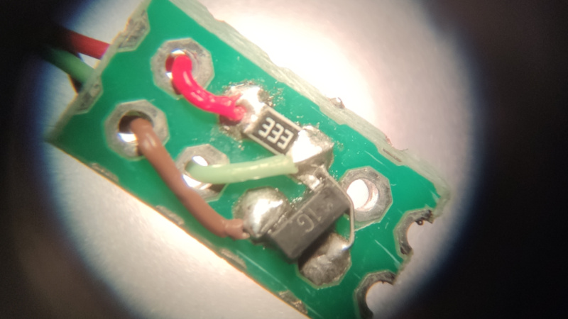
One of the joys of writing up the entries for the 2025 Component Abuse Challenge has come in finding all the different alternative uses for the humble transistor. This building block of all modern electronics does a lot more than simply performing as a switch, for as [Aleksei Tertychnyi] tells us, it can also function as a temperature sensor.
How does this work? Simple enough, the base-emitter junction of a transistor can function as a diode, and like other diodes, it shows a roughly 0.2 volt per degree voltage shift with temperature (for a silicon transistor anyway). Taking a transistor and forward biasing the junction with a 33 K resistor, he can read the resulting voltage directly with an analogue to digital converter and derive a temperature reading.
The transistor features rarely as anything but a power device in the projects we bring you in 2025. Maybe you can find inspiration to experiment for yourself, and if you do, you still have a few days in which to make your own competition entry.


A 33 kelvins resistor you say???
It’s just that cool.
Also, I would not call this abuse, this is a pretty typical use case. I have seen many devices which uses diodes or transistors as temperature sensors. I even designed one. A diode is cheaper than a thermistor.
I saw this solution in LENOVO computers
I was about to say… Saw this in at least an old dell optiplex and an ancient gateway 2000
Is it really abuse when it’s industry standard practice? It’s nice to spread awareness of it, of course, but there’s many an app note about this and you can even buy ICs that automate the process if you want better accuracy and direct digital readout.
Exposing a PN junction to test pins on an IC is a common way of externally measuring die temp. And if the IC doesn’t have one, and you have a spare input pin, you can measure the junction voltage across the ESD protection TVS diode.
Using ESD protection as T sensor – that’s what I call proper abuse :)
Using the -2 mV/deg C characteristic of a PN junction is really simple, but that requires calibration for each circuit to get even crude accuracy. The initial offset can be pretty bad. It’s maybe useful for a one-time lab circuit, but probably not as a real product.
More elegant is the delta-Vbe method, which measures the collector-emitter voltage at two different collector currents, and then the difference of those voltages is precisely proportional to Kelvin temperature. You can generally get 1-2 degree accuracy without calibration.
People have come up with a variety of circuits to do that, generally a bit complicated.
A good reminder that that -2 mV/K is on top of the log response of the forward voltage wrt current.
Note that this applies to a transistor, where the collector and base are shorted together, leaving just the base:emitter diode junction, so Vbe = Vce and “collector current” really means “base current”.
You can do it the simple way and measure the offset to your favorite zero temperature point (“calibrate” it), and take the -2 mV/K slope (and optionally calibrate that) to estimate the temperature. Or do as Carl says and take the measurements at two different currents and get a pretty good notion of what the offset is from the measured voltage vs. log of the current ratio.
Note you still need a calibration, to get that proportionality constant, so this doesn’t rescue you from that. It does reduce your exposure to device-to-device variability, so you might get away with doing this just once for a design rather than for each temperature sensor you install.
You already get a long way to repeatability by using a transistor instead of a diode though: Process variability is generally tighter.
By measuring at two different currents you can also eliminate the wire resistance of remote sensors. The voltage drop of wire is linear with current, not so with pn junctions.
Back in the day I had a copy of The VIC-20 Interfacing Book. One of the projects was a diode-based temperature sensor. To make it easier to measure, it used about eight diodes in series.
This really isn’t abuse, I’ve been using transistors Base Emitter temp coefficient for years. Using a VBE multiplier you can get what ever temp coefficient you want, then offset that voltage to gain a known voltage with a set temperature coefficient. I used these in many circuits like lead acid battery charges for ensuring the float voltage of the battery has the correct output to ensure the battery is charged correctly for its environment. This isn’t new, abuse or a breakthrough.
Back in the old days, the OC71 had a glass package painted black. If you scraped the paint off you could use it as a phototransistor. Just sayin’….
0.2 volt/deg? Approx. 2 mV/deg
Wasn’t that the semi-official solution to using non-Apple hard drives in Apple iMacs to stop the system fan from going turbo?
I have but one thing to say, 0.2 volts is not 2mV. 0.2 volts is 200mV. Unless something changed and I wasn’t told.
It’s a simple transistor a little rusty, a little bit old, but it’s a transistor! 😃 cheers to this old transistor
Didn’t Tektronix do this for some of their temperature probes decades ago?
I’m sure I remember seeing this for some TM500 digital multimeter modules, with instructions in the service manual about how to make your own.
That’s nothing new. Seen it used in several brands of enterprise servers as well.