
If you take a look around you, chances are pretty good that within a few seconds, your eyes will fall on some kind of electrical connector. In this day and age, it’s as likely as not to be a USB connector, given their ubiquity as the charger of choice for everything from phones to flashlights. But there are plenty of other connectors, from mains outlets in the wall to Ethernet connectors, and if you’re anything like us, you’ve got a bench full of DuPonts, banana plugs, BNCs, SMAs, and all the rest of the alphabet soup of connectors.
Given their propensity for failure and their general reputation as a necessary evil in electrical designs, it may seem controversial to say that all connectors are engineered to last. But it’s true; they’re engineered to last, but only for as long as necessary. Some are built for only a few cycles of mating, while others are built for the long haul. Either way, connectors are a great case study in engineering compromise, one that loops physics, chemistry, and materials science into the process.
A Tale of Two Connectors
While there’s a bewildering number of connectors available today, most have at least a few things in common. Generally, connectors consist of one or more electrically conductive elements held in position by an insulating body of some sort, one that can mechanically attach to another body containing more conductive elements. When the two connectors are attached, the conductive elements come into physical contact with each other, completing the circuit and providing a low-resistance path for current to flow. The bodies also have to be able to separate from each other when the connections need to be broken.
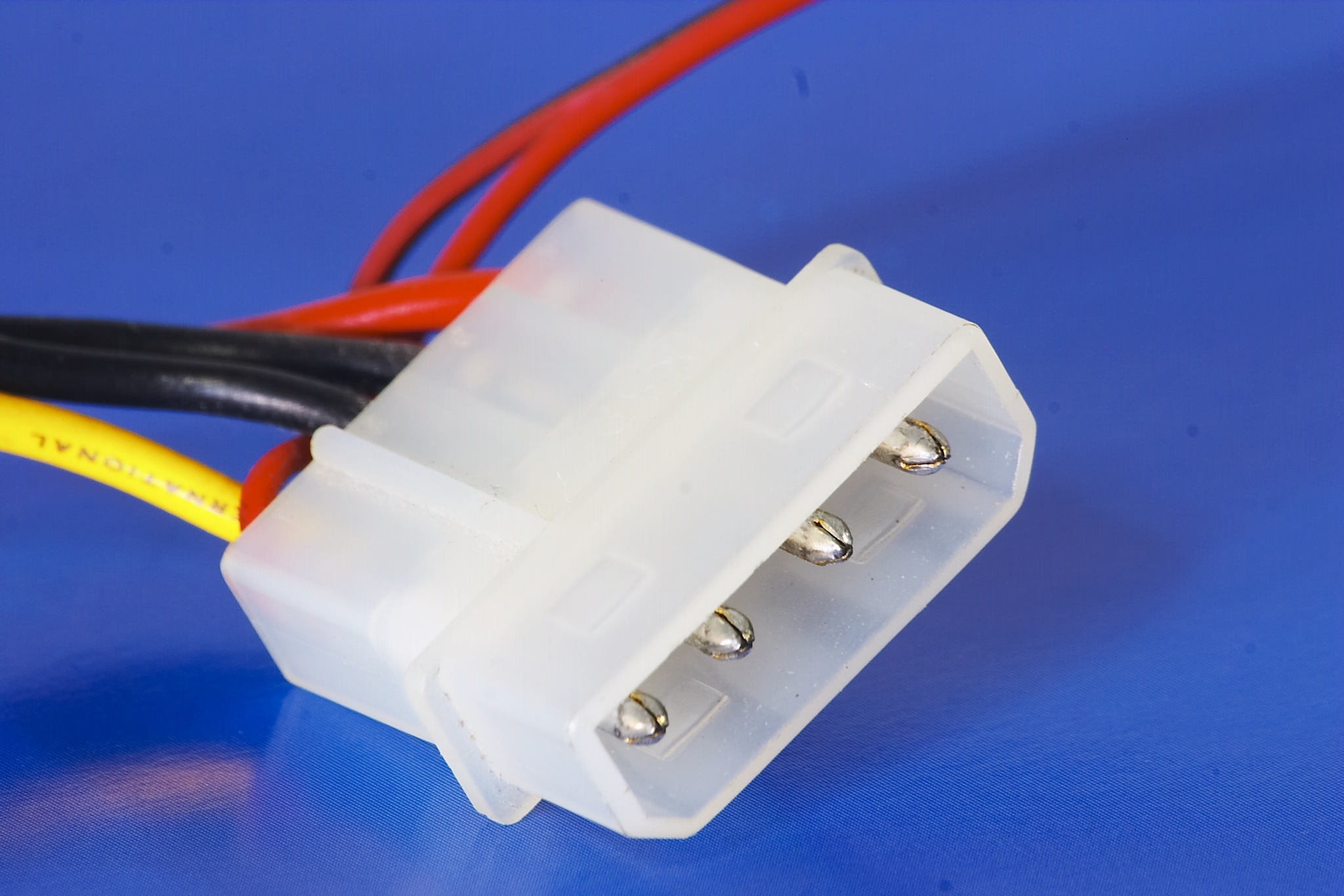
For as simple as that sounds, a lot of engineering goes into making connectors that are suitable for the job at hand. The intended use of a connector dictates a lot about how it’s designed, and in terms of connector durability, looking at the extremes can be instructive. On one end of the scale, we might have something like a Molex connector on a wiring harness in a dishwasher. Under ideal circumstances, a connector like that only needs to be used once, in the factory during assembly. If the future owner of the appliance is unlucky, that connector might go through one or two more mating cycles if the machine needs to be serviced at some point. Either way, the connector is only going to be subjected to low single-digit mating cycles, and should be designed accordingly
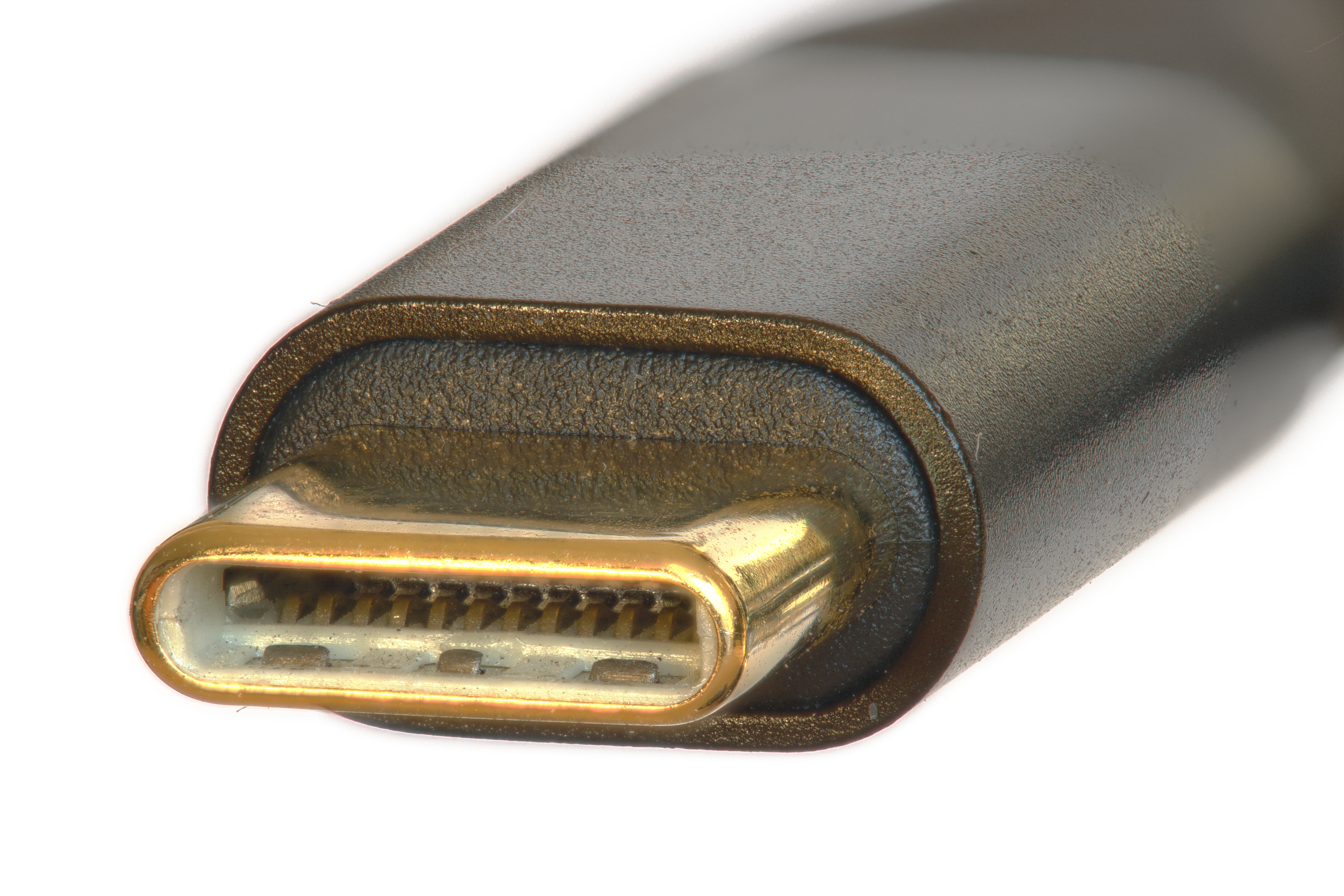
On the other end of the mating-cycle spectrum would be something like the USB-C connector on a cell phone. Assuming the user will charge the phone once a day, the connector might have to endure many thousands of mating cycles over the useful life of the phone. Such a connector has a completely different use case from a connector like that Molex, and very different design constraints. But the basic job — bringing two conductors into close contact to complete a low-resistance circuit, and allow the circuits to be broken only under the right circumstances — is the same for both.
But what exactly do we mean by “close contact”? It might seem obvious — conductors in each half of the connector have to touch each other. But keeping those conductors in contact is the real trick, especially in challenging environments such as under the hood of a car or inside a CNC machine, where vibration, dust, and liquid intrusion can all come together to force those contacts apart and break the circuit while it’s still in use.
Why Be Normal?
To keep contacts together, engineers rely on one of the simplest mechanisms of all: springs. In most connectors, the contacts themselves are the sprung elements, although there are connectors where force is applied to the contacts with separate springs. In either case, the force generated by the spring pushes the contacts together firmly enough to ensure that they stay connected. This is the normal force, called so because the force is exerted perpendicular to the plane of contact when the connector is mated.
Traditionally, normal force in connector engineering is expressed in grams, which seems like an affront to the SI system, where force is expressed in Newtons. But fear not — “grams” does not refer to the mass of a contact, but rather is shorthand for “gram-force,” the force applied by one gram of mass in a one g gravitational field. So, an “80 gram” contact is really exerting 0.784 N of normal force. But that’s a bit clunky, especially when most connectors have normal forces that are a fraction of a Newton. So it ends up being easier to refer to the grams part of the equation and just assume the acceleration component.
The amount of normal force exerted by the contacts is a critical factor in connector design, and has to be properly scaled for the job. If the force is too low, it may increase the resistance of the circuit or even result in intermittent open circuits. If the force is too high, the connector could be difficult to mate and unmate, or the contacts could wear out from excess friction.
Since the contacts themselves are usually the springs as well as the conductors, getting the normal force right, as well as ensuring the contacts are highly conductive, is largely an exercise in materials science. While pure copper is an excellent conductor, it is not elastic enough to provide the proper normal force. So, most connectors use one of two related copper alloys for their contacts: phosphor bronze, or beryllium copper. Both are excellent electrical and thermal conductors, and both are strong and springy, but there are significant differences between the two that make them suitable for different types of connectors.
As the name implies, phosphor bronze is an alloy of phosphorus and bronze, which itself is an alloy of copper and tin. To make phosphor bronze, about 0.03% phosphorus is added to pure molten copper. Any oxygen dissolved in the copper reacts with the phosphorus, making phosphorus pentoxide (P2O5), which can be easily removed during refining. About 2% tin is added along with about 10% zinc and 2% iron to make the final alloy, which is easily cast into sheets or coil stock.
While far superior to pure copper or non-phosphor bronze for use in contacts, phosphor bronze is, at best, a compromise material. It’s good enough in almost all categories — strength, elasticity, conductivity, wear resistance — but not really great in any of them. It’s the “Jack of all trades, master of none” of the electrical contact world, which, coupled with its easy workability and low cost, makes it the metal of choice for the contacts in commodity connectors. If a manufacturer is making a million copies of a connector, especially ones that are cheap enough that nobody will cry too much if they have to be replaced, chances are good that they’ll choose phosphor bronze. It’s also the alloy most likely to be used for connectors intended for low mating-cycle applications, like the aforementioned dishwasher Molex.
For more mission-critical contacts, a different alloy is generally called for: beryllium copper. Also known as spring copper, beryllium copper contains up to about 3% beryllium, but for electrical uses, it’s usually around 0.7% with a little cobalt and nickel added in. Beryllium copper is everything that phosphor bronze is, and more. It’s stronger and springier, it’s a far better electrical conductor, and it also has a better ability to withstand creep under load. Also known as stress relaxation, creep under load is the tendency for a spring to lose its strength over time, which reduces its normal force. Phosphor bronze has pretty good stress relaxation resistance, but when it heats up past around 125°C, it starts to lose spring force — not ideal for high-power applications. Beryllium copper is easily able to withstand 150°C or more, making it a better choice for power connectors.
Beryllium copper also has a higher elastic modulus than phosphor bronze, which makes it easier to create small contacts that still have enough normal force to maintain good contact. Smaller is better when it comes to modern high-density connectors, so you’ll often see beryllium copper used in fine-pitch connectors. It also has better fatigue life and tends to maintain normal force over repeated mating cycles, making it desirable for connectors that specify cycle lives in the thousands. But just because it’s desirable doesn’t make it a shoo-in — beryllium copper is at least three times more expensive than phosphor bronze. That means it’s usually reserved for connectors that can justify the added expense.
Noble Is Only Skin Deep
No matter what the base metal is for connector contacts, chances are good that the finished contact will have some sort of plated finish. Plating is important because it protects the base metal from oxidation, as well as increasing the wear resistance of contacts and improving their electrical conductivity. Plating metals fall into two broad categories: noble (principally gold, with silver used sometimes for high-power connectors, as well as palladium, but only very rarely) and non-noble platings.
Noble metal finishes are quite common in high-density connectors, RF applications, and high-speed digital circuits, as well as high-reliability applications and connectors that are expected to have high mating cycles. But at the risk of stating the obvious, gold is expensive, so it’s used only on connectors that really need it. And even then, it’s very rare that the entire contact is plated. While that would be incredibly expensive — gold is currently pushing $4,000 an ounce — the real reason is that gold isn’t particularly solderable. So generally, selective plating is used to deposit gold only on the mating surfaces of contacts, with the tail of the contact plated in a non-noble metal to improve solderability.
Among the non-noble finishes, tin and tin alloys are the first choice. Aside from its excellent solderability, tin alloys do a great job at protecting the base metal from corrosion. However, the tin plating itself begins to oxidize almost immediately after it’s applied. This would seem to be a problem, but it’s easily addressed by using more spring force in the contacts to break through the oxide layer to fresh tin. Tin-plated contacts typically specify normal forces of 100 grams or more, while noble metal contacts can get by with 30 grams or less. Also, tin contacts require much thicker plating than noble metal finishes. Tin is generally specified for commodity connectors and anywhere the number of mating cycles is likely to be low.
Don’t You Fret
Although corrosion is obviously something to be avoided, the real enemy when it comes to connector durability is metal-on-metal contact. The spring pressure between contacts unavoidably digs into the plating, and while that’s actually desirable in tin-plated contacts, too much of a good thing is bad. Digging past the plating into the base metal marks the end of the road for many connectors, as the base metal’s relatively lower conductivity increases the resistance of the connection, potentially leading to intermittent connections and even overheating. Again, noble metals perform better in this regard, at least in the long run, as their lower normal force reduces friction and results in a longer-lived contact.
There’s another metallurgical phenomenon that can wreak havoc on connectors: fretting. Fretting is caused by tiny movements of the contacts against each other, on the order of 10-7 meters, generally in response to low-g vibrations but also as a result of thermal expansion and contraction. Fretting damage occurs when the force of micromotions between contacts exceeds the normal force exerted between them. This leads to one contact sliding over the other by a tiny amount, digging a trench through the plating metal. In tin-plated contacts, this exposes fresh tin, which oxidizes instantly, forming an insulating surface. Further micromotions expose more fresh tin, which leads to more oxides. Eventually the connection fails due to high resistance. Fretting is insidious because it happens even without a lot of mating cycles; all it takes is a little vibration and some time. And those are the enemies of all connectors.


Some additional notes:
The Molex as used in computer HDD’s (it’s becoming obsolete now…) can be improved by first mating the connector, and then injecting some hot glue into the back end. This is useful if you’re tinkering a lot on your PC hardware.
Some connector types, such as flatcable connectors, “square pin” PCB headers and DIN41612 can be bought in different durability classes. The cheapest may be specified for 20 (or less) mating cycles, while the higher endurance version may be specified for a few thousand mating cycles.
A few years ago there was a huge problem with power connectors on high performance video cards. There were thousands of complaints about melting connectors. And that is for video cards in the EUR 100 to EUR 2000 price range. I don’t have such a card myself, so I did not keep track of further details.
There would be no issue with GPUs if they used simple nut-and-bolt eye connector. Gamers can memorize stats of 100s of in-game weapons and thousands addons and skins for each, but unfortunately they are too dumb to understand that “torque to 25 Nm” means torque to 25 Nm. Not more, not less. There would be many incidents with connectors either becoming crushed from fatsos tightening them with all their fat might and $900 PRO GAMING WRENCH, or becoming loose and shorting stuff out inside the case if torqued with some chinese box end wrench made out of the finest tofu dreg. This is why NVIDIA went with this wimpy, idiot-proof connector.
Do you have a link for the unlimited precision torque wrench implied in your post?
Us ‘dumb’ people have never heard of such a thing.
JTFC I believe nonsense like ‘You cannot achieve perfection, only bankruptcy.’
I doubt that ’25’ has 2 significant digits.
Maybe with a really nice wrench and really clean surfaces.
‘They’ need to move more of the power supply to the graphics board.
Feed it AC.
The boards already have a stack of regulators, for the variable DC voltage core.
How many pads on the actual GPU are carrying power?
Too lazy to Google it.
That has to be right up against the edge of ‘works’ too.
Simple solution is to include the torque wrench with the card. AMD does this with their threadripper CPUs so the cpu to socket connection has the right force.
3Dfx did it on Voodoo 5 prototypes.
Lots of PCs from the end of the 90s had flimsy PSUs that couldn’t supply much on the +12V rail, so 3Dfx decided to ship an external 12V PSU to supply only the graphics card.
Dunno about rings, there are at least 4 connectors that are an improvement without screw fasteners.
First Molex in a 4.2mm pitch instead of 3.0mm. (AKA what was used previously, but in Dual “CPU” pinout.)
Second XT90
Third Anderson 150A
Fourth is a board edge connector, which some cards are already using.
In fact the last one the same technology 1000+ watt hot-swappable server power supplies use.
Also the 12v specification is fairly ridiculous, Laptops use by and large similar DC-DC circuits but are very commonly using 20v, possibly 24v which would do a lot to mitigate issues. Although it would be smart to use 13.2v power, as it likely is already compatible with a 12v video card to a reasonable degree.
A lack of bolts isn’t remotely the problem with the connector design. There are plenty of connectors rated for the power requirements in a compact implementation, but Nvidia in particular refused to even bother. That’s it, the entire story with no extra drama.
lol well said
Those GPU connectors are still an issue. There have been numerous “fixes” that are little better than janky hacks, and connectors are still routinely melting. In multi-thousand-dollar graphics cards. Ridiculous.
It’s almost like they’re using the connectors at the limit of their current carrying capacity. And then they wonder why even the slightest issues, or even no issue at all, cause them to melt and catch fire…
the new connectors really aren’t that great of an advancement either. they can only do 600w and its a composite connector, which makes it really stiff. nothing makes gamers bend cables like overkill strain relief and lack of clearance in most cases. cards are getting taller and they make the “genius” move of putting the power connector right at the top of the card where it is in very close proximity to the side panel, or on the front edge where there is also less clearance with 3-fan cards. putting the connector on the pcb face, either at the front or back, would make more sense.
i think i would have preferred a 16-connector cable with a single contact type, and with sense pins at the ends, this would have made the cables fold easier and would have been a better indication of full contact by the sense pins.
dont get me started about the structural requirements of a chonky boy card supported by 2 screws and a pcie connector. my mini-itx mobos are lighter and get 4 good screws in the corners (i also kind of want to see cpu socket standoffs that let you hard mount your cpu cooler through the mobo directly into the chassis).
“Only 600W” is no small feat when you’re doing it with low voltage DC.
That’s 12V x 50 Amps. You could weld steel with that.
It’s a faulty design. A large part of the problem is that they put the connector on the wrong part of the card, right in your face,, resulting in people wanting to put tight bends on the cable and put a ton of strain on it, to hide the cable. I refuse to buy a card like that.
The list of problems with the design is long indeed, but Nvidia doesn’t care about consumer problems any more.
I hope there is a way to hack an HDMI connector onto all the AI cards NVidia sold in the last two years.
It is possible to connect the monitor to the integrated GPU and pass the video to it over the PCIe connection. There will be a performance penalty, but at least you can shut down the power hungry GPU when you’re not gaming.
…..mmmm nearly all my iPhone lightning cables fail at the connector from normal and carefull use. Plastic sheath rotting, oxidized pads, shorting internal wires. Total rubbish.
I still get a chuckle out of this kind of whinge and seeing people with their little white cubes tethered to outlets on pillars in hallways of public places. I have been using Android devices with wireless charging for over a decade and unless I forget to put my phone on the charger at night, I don’t worry about battery life. I use a rubber plug in my charging port so it’s ready to go in case I need to attach a device such as a camera. It’s liberating. It’s how life should have been for the past decade. Cory Doctorow has a word for such encumbrances.
iPhones have wireless charging too, though they don’t shout about it – I’d had mine for ages before I realised.
But iPhone or Android, it’s less efficient, and – whilst it’s small – we should probably care about that.
Battery life is very dependent on how you use your phone. I only need to charge my iPhone during the day if I use it for satnav (full brightness screen) for a long drive.
Weirdly, I’ve had one lightning cable fail in however long we’ve been using them. Apple ones are fine; Amazon ones are fine. Even most ali ones are fine.
In no small part because Apple still prioritise beauty over function – that’s not a dig, a lot of their hardware is fantastically engineered, but especially for the consumer-facing bits they will take the compromise every time as long as it looks sexy.
You are hilariously out of date. Apple has been farming it their design since before Jobs died, before the 2000 Apple design awards even. So no, they prioritise paying for an appealing design, but it’s not “fantastically engineered”, just pretty good on average, with a nice attention to aesthetics. Just look at the failure rates of their onboard security chips.
Consider that they are very effective at suppressing dissenting voices in their user base because it’s a close ecosystem.
Newbie error: when assembling connectors, soldering the wire to the pins anneals the metal and oxidizes the surfaces. The result is a loss of spring pressure and contact issues due to accelerated surface corrosion. The connectors soon fail.
Always crimp.
The annealing temperature for phosphor bronze, the usual spring contact base metal, is more than 480 C, well in excess of typical soldering temperatures. Spring steels are even higher.
Technically, but changes happen at lower temperatures between 200-400C. The actual precise term is tempering.
To be more exact, the barrel side of the contact pair was work-hardened when it was folded in the machine that made it, and when you heat it up the internal stresses are relieved and the metal is softened slightly, and it becomes slightly ductile again. That means when you insert the pin, and wiggle it about a little, it expands and becomes loose.
Always crimp with the right tool :)
And calibrate it according to the manufacturer’s schedule…
And step by step a $50 sumo robot for a local competition becomes a $5000 project, just because of four Molex KK connectors.
as an sff builder i was looking to crimp my own cables, but opted against it after seeing the prices of some of the housings/pins. cable smushing it is.
As I learned when I was 14…
It’s also almost impossible the solder all the connections correctly without melting the plastic connector.
Also the ends are a bitch to solder too, as they are designed to cut through the ribbon cable.
In my defense I only ruined one cable and connector before figuring it out.
Correct crimp tool is a bench vise.
i 3d printed a cable crimping tool and it turned out to be a total flop, i ended up tapping it in with a mallet. bench vise is a good tip (i have one of those now).
wasn’t soldering the connectors part of the 12VHPWR spec?
always known that high quality crimps are the way to go. soldering cables makes them inflexable and results in cracking eventually.
If it’s meant for soldering, do, but follow the specified temperatures and heating times.
If it’s meant for crimping, never solder. This is usually in-line connectors rather than something you’d attach to a board.
Don’t overlook the RJ-series connectors (RJ11/12/45) — industrial versions are rated to about 10,000 insertions and roughly 1–1.5 A per contact.
By comparison, the old “Cannon” D-sub style used on spacecraft — and later popularized on everyday serial cables — was typically built for high-reliability 5–7 A contacts and 10k+ cycles, with screw-lock retention for vibration.
That’s what you get when you have one entity designing a proper connector.
When you have a fscking design committee, that’s when you get the abomination of USB.
I mean, how else can you come up with a connector (USB A male) that will happily and snugly mate with the Ethernet connector (RJ45 jack) next to it on a panel?
The USB A connector identifies as Ethernet you transphobe!
i still want an industrial rated usb-c. same connector just make it bigger so the machine vibrations dont fatigue the solder. or embed it in a d block with a few extra power pins.
Kind of apples:oranges but: If you want the size and speed plus mechanical fixation but don’t need the actual USB protocol and associated overheads (and can run separate power, which you should anyway), consider SpaceWire.
There are industrial connectors that just put a robust housing around an otherwise standard USB C connector. You can actually find them for a lot of different computer connectors.
i miss d-sub connectors. bring them back!
They haven’t completely gone away, they are just a lot less common now.
The intro to this article nicely lays out the concept of planned obsolescence, though not by name which is a shame as it’s gotten a bad rap over the years.
The general public heard the term and twisted it into the idea of things being “built to fail”, which is nonsense as the article explains. It’s just that not everything needs to be engineered for a 50-year lifespan or 10,000 actuations, and to design EVERYTHING to stand up to that kind of use would be overengineering much of what our everyday tech is made from. (Adding bulk, weight, and cost in the process.)
God DAMMIT Hackaday! This wasn’t a reply to Fabo, but because I accidentally tapped “Reply” on their comment, them cancelled that reply, before leaving my comment in the box at the bottom of the page, here it sits, misfiled as usual.
Excellent cover artwork, I can imagine it animated. Very Gerald Scarfe / Pink Floyd The Wall. Excuse me, I need to go and put some music on now…
If you really want a high reliability connector (and have a ample budget)…. “The hyperboloid contacts used in the Smiths Interconnect L Series connectors are typically rated for up to 100,000 mating cycles with minimal degradation in performance. ” We used to use these connectors for building reusable fixturing that had to withstand severe environments of humidity and temperature range inside an environmental testing chamber. Probably almost aerospace quality.
There are other options for the Hyperboloid connectors. I know Smiths have been sold so somewhat uncertain. IEH Corp are another manufacturer of the hyperboloid connectors with as good a range as Smiths. From what I understand the lead times etc are far better as well. They are an American manufacturer but gaining traction in the UK and Europe.
AKA Hypertronix connectors. We used them on fixtures for testing implantable medical devices. Cost wasn’t a concern, but as I remember it, lead time could be many weeks or even months, so having plenty of safety stock was a prudent strategy.
Micro-USB was the creation of an evil, malevolent entity with the intent to bring into being as much subtle human suffering as possible. I believe that this being was also responsible for the ring-road/beltway systems surrounding almost every major city across the world and K-Pop.
Some 25 years ago I worked on a project were we had to make new spare boards for a oil/gas power station that was still in use but past its expected life. The original Westinghouse boards were no longer available and some components didn’t even exist anymore, so needed to be redesigned to have the same behavior.
All the cards were to go into a rack, and the mating connectors were not regular of the shelf, and yes, these were also out of production and the original manufacturer didn’t even exist anymore.
Through quite a lot of research and luck, we found a company that had acquired the tooling for these parts, and agreed to make some connectors for us in exchange for a big lump of cash.
The connectors were quite something. The contacts were not quite male or female and were identical for both mating parts. Each contact was shaped as a fork, and the inside edges of the fork were beveled at 45 degrees. The contact would mate at 90 degrees of each ensuring that there would always be four surfaces in contact for each pin.
I keep wanting to try and see if I can get full speed and functionality from USB-C routed through a D-sub connector, but I don’t actually have a use case other than wanting to have the highest-bandwidth DB-25 connection in history.
I doubt it will work above 480 mbps because of the impedance mismatch. It may be possible using a d-sub with coaxial connections, but you would need suitable matching circuitry on each side of the connector. You could also build a connector from scratch that looks like a DB-25, but has proper 90 ohm differential pairs in it.
Why grams and not milli-Newtons or centi-Newtons?
I’ve seen ratchet straps sold with deca-Newton ratings so it wouldn’t be without precedent.
The intro to this article nicely lays out the concept of planned obsolescence, though not by name which is a shame as it’s gotten a bad rap over the years.
The general public heard the term and twisted it into the idea of things being “built to fail”, which is nonsense as the article explains. It’s just that not everything needs to be engineered for a 50-year lifespan or 10,000 actuations, and to design EVERYTHING to stand up to that kind of use would be overengineering much of what our everyday tech is made from. (Adding bulk, weight, and cost in the process.)
Was in the Air Force and took a joint NASA Air Force course on connectivity. It was really interesting to learn that sometimes no mating cycles can be a problem due to lack of the wiping action of the mating cycles. Also learned the most reliable connectors relied on separating springs from the pins themselves and used springs to push hard pins into machined tapered sockets. Was also told to never ever add solder to a crimped connection and crimped is highly preferred over soldering. To the person above melting d subs….use crimped pins or get your iron much much hotter. Pre tin wire and cup. Touch iron to cup to melt and push wire in. Speed is your friend here. Should not take longer than one second. When you take too long you also creep heat the wire up under the insulation which causes brittle wire due to solder creep. Heating the socket pulls solder toward the socket instead of up the wire. Mil-spec d sub crimped pins are my favorite type. The closed barrel type of pins with the four way indenting crimper.
I’ll tell you the worst connector ever invented. The car trailer connector. They are hard to connect and remove, they rarely work for all the signals. They are unnecessarely big and the shell breaks easily. And they just keep piling more signals and connections into them.
Nope. The “Molex” connector shown here is not a Molex-connector. It’s made by AMP (now TE connectivity) https://commons.wikimedia.org/wiki/File:Amp_and_Molex_Connectors.jpg
They’re all colloquially known as “Molex connectors”.
https://en.wikipedia.org/wiki/Molex_connector