Dead Solar Panels Are The Hottest New Recyclables

When it comes to renewable energy, there are many great sources. Whether it’s solar, wind, or something else, though, we need a lot of it. Factories around the globe are rising to the challenge to provide what we need.

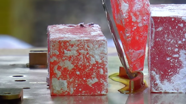
We can build plenty of new solar panels, of course, but we need to think about what happens when they reach end of life. As it turns out, with so much solar now out in the field, a major new recycling industry may be just around the corner.

Continue reading “Dead Solar Panels Are The Hottest New Recyclables”

Make Your Desoldering Easier By Minding Your Own Bismuth

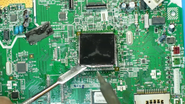
Any video that starts with a phase diagram has instantly earned our attention. Admittedly, we have a pretty low bar for that kind of stuff, but eye candy aside, [Robin Debreuil]’s quick outline of his technique for desoldering with the help of bismuth is worth watching.

Aside from its use in those pink gloopy solutions one takes for an upset stomach, bismuth has a lot of commercial applications. For the purposes of desoldering, though, its tendency to lower the melting point of tin and tin alloys like solder is what makes it a valuable addition to the toolkit. [Robin] starts with a demonstration of just how far a little bismuth depresses the melting point of tin solder — to about 135°. That allows plenty of time to work, and freeing leads from pads becomes a snap. He demonstrates this with some large QFP chips, which practically jump off the board. He also demonstrates a neat technique for cleaning the bismuth-tin mix off the leads, using a length of desoldering braid clamped at an angle to the vertical with some helping-hands clips. The braid wicks the bismuth-tin mix away from the leads along one side of the chip, while gravity pulls it down the braid to pool safely on the bench. Pretty slick.

Lest leaded solder fans fret, [Robin] ensures us this works well for lead-tin solder too. You won’t have to worry about breaking the bank, either; bismuth is pretty cheap and easily sourced. And as a bonus, it’s pretty non-toxic, at least as far as heavy metals go. But alas — it apparently doesn’t machine very well.

Continue reading “Make Your Desoldering Easier By Minding Your Own Bismuth”

Soldering Like It’s 205 BC

Did you ever stop to think how unlikely the discovery of soldering is? It’s hard to imagine what sequence of events led to it; after all, metals heated to just the right temperature while applying an alloy of lead and tin in the right proportions in the presence of a proper fluxing agent doesn’t seem like something that would happen by accident.

Luckily, [Chris] at Clickspring is currently in the business of recreating the tools and technologies that would have been used in ancient times, and he’s made a wonderful video on precision soft soldering the old-fashioned way. The video below is part of a side series he’s been working on while he builds a replica of the Antikythera mechanism, that curious analog astronomical computer of antiquity. Many parts in the mechanism were soldered, and [Chris] explores plausible methods using tools and materials known to have been available at the time the mechanism was constructed (reported by different historians as any time between 205 BC and 70 BC or so). His irons are forged copper blocks, his heat source is a charcoal fire, and his solder is a 60:40 mix of lead and tin, just as we use today. He vividly demonstrates how important both surface prep and flux are, and shows both active and passive fluxes. He settled on rosin for the final joints, which turned out silky smooth and perfect; we suspect it took quite a bit of practice to get the technique down, but as always, [Chris] makes it look easy.

If you’d like to dig a bit deeper into modern techniques, we’ve covered the physics of solder and fluxes in some depth. And if you need more of those sweet, sweet Clickspring videos, we’ve got you covered there as well.

Continue reading “Soldering Like It’s 205 BC”

Tinning Solution From The Hardware Store

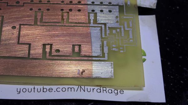
Making your own printed circuit board at home often leads to a board which looks homemade. Exposed copper is one of the tell-tale signs. That may be your aesthetic and we won’t cramp your style, but exposed copper is harder to solder than tinned copper and it likes to oxidize over time. Tinning at home can bring you a step closer to having a full-featured board. In the video after the break, famed chemist [nurdrage] shows us how to make tinning solution at home in the video below the break.

There are only three ingredients to make the solution and you can probably find them all at a corner hardware store.

  • Hydrochloric acid. Also known as muriatic acid.
  • Solid lead-free solder with ≥ 95% tin
  • Silver polish containing thiourea

Everything to pull this off is in the first three minutes of the video. [nurdrage] goes on to explain the chemistry behind this reaction. It doesn’t require electricity or heat but heat will speed up the reactions. With this kind of simplicity, there’s no reason to make untinned circuit boards in your kitchen anymore. If aesthetics are very important, home tinning yourself allows you to mask off certain regions and have exposed copper and tin on the same board.

[nurdrage] is no stranger to Hackaday, he even has an article here about making your own PCB etchants and a hotplate to kick your PCB production into high gear.

Thanks for the tip, [drnbutyllithium].

Continue reading “Tinning Solution From The Hardware Store”

Grow Your Own Tin Crystals

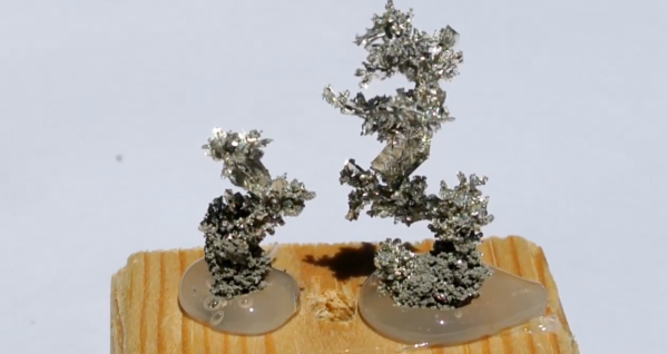
[The Plutonium Bunny] saw homegrown tin crystals on YouTube and reckoned he could do better—those crystals were flimsy and couldn’t stand up outside of the solution in which they were grown. Having previously tackled copper crystals, he applied the same procedure to tin.

Beginning with a 140 ml baby food jar filled with a solution of tin II chloride, 90 grams per liter, with a small amount of HCl as the electrolyte. A wire at the bottom of the jar was connected to a blob of tin and served as the anode, while the cathode, a loop of tin, stuck down from above. A LM317-based adjustable voltage regulator circuit was used to manage the power running through the solution. Because [The Plutonium Bunny]’s technique involves days or even weeks of very low current, he used six diodes to drop the circuit’s voltage from 1.5 V to 0.25 V, giving him around 13 mA.

His first attempt seemed to go well and he got some nice shiny crystal faces, but he couldn’t get the current bellow 10 mA without it dropping to the point where no tin was depositing. Rather than reset the experiment he made some changes to the project: he changed the solution by removing 30 ml of the electrolyte and topping it off with water. He also made a gentle agitator out of a DC motor and flattened plastic tube from a pen, powering it with another low-voltage LM317 circuit so he could get the lowest RPM possible.

With this new setup [The Plutonium Bunny] began to get much  better results, proving his hypothesis that low current with a lower concentration of Sn2+ was the ticket for large crystal growth. We featured his copper crystal experiments last year and he’s clearly making good progress! Video after the break.

Continue reading “Grow Your Own Tin Crystals”

What The Flux: How Does Solder Work Anyway?

I’ve been soldering for a long time, and I take pride in my abilities. I won’t say that I’m the best solder-slinger around, but I’m pretty good at this essential shop skill — at least for through-hole and “traditional” soldering; I haven’t had much practice at SMD stuff yet. I’m confident that I could make a good, strong, stable joint that’s both electrically and mechanically sound in just about any kind of wire or conductor.

But like some many of us, I learned soldering as a practical skill; put solder and iron together, observe results, repeat the stuff that works and avoid the stuff that doesn’t. Seems like adding a little inside information might help me improve my skills, so I set about learning what’s going on mechanically and chemically inside a solder joint.

Continue reading “What The Flux: How Does Solder Work Anyway?”

Solder At Room Temperature

Have you ever seen the science experiment (or magic trick?) where you get water supercooled to where it isn’t frozen, but then it freezes when you touch it, pour it, or otherwise disturb it? Apparently, ice crystals form around impurities or disturbances in the liquid and then “spread.” A similar effect can occur in metals where the molten metal cools in such a way that it stays melted even below the temperature that would usually cause it to melt.

[Martin Thuo] at Iowa University used this property to make solder joints at room temperature using Field’s metal (a combination of bismuth, indium, and tin). The key is a process that coats the molten metal with several nanolayers that protect it from solidifying until something disturbs the protective layer.

Continue reading “Solder At Room Temperature”