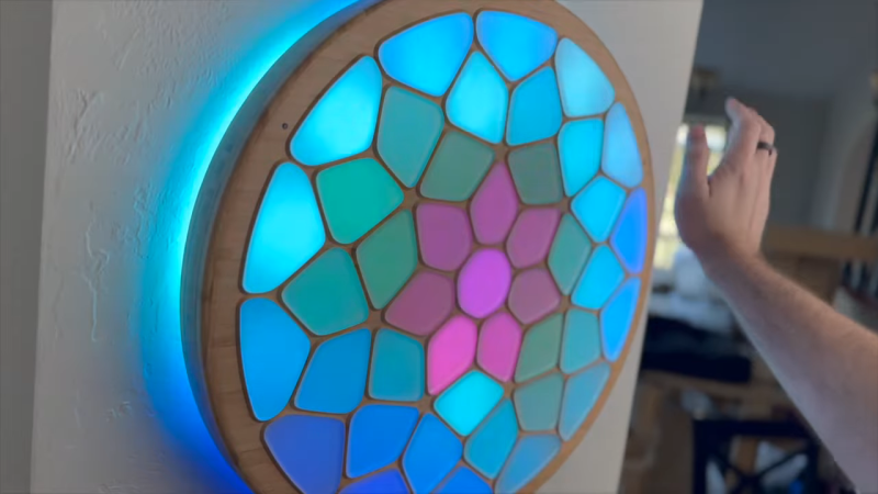
[Voria Labs] has created a whole bunch of artworks referred to as Lumanoi Interactive Light Sculptures. A new video explains the hardware behind these beautiful glowing pieces, as well as the magic that makes their interactivity work.
The basic architecture of the Lumanoi pieces starts with a custom main control board, based around the ESP-32-S3-WROOM-2. It’s got two I2C buses onboard, as well as an extension port with some GPIO breakouts. The controller also has lots of protection features and can shut down the whole sculpture if needed. The main control board works in turn with a series of daisy-chained “cell” boards attached via a 20-pin ribbon cable. The cable carries 24-volt power, a bunch of grounds, and LED and UART data that can be passed from cell to cell. The cells are responsible for spitting out data to addressable LEDs that light the sculpture, and also have their own microcontrollers and photodiodes, allowing them to do all kinds of neat tricks.
As for interactivity, simple sensors provide ways for the viewer to interact with the glowing artwork. Ambient light sensors connected via I2C can pick up the brightness of the room as well as respond to passing shadows, while touch controls give a more direct interface to those interacting with the art.
[Voria Labs] has provided a great primer on building hardcore LED sculptures in a smart, robust manner. We love a good art piece here, from the mechanical to the purely illuminatory. Video after the break.


Just a video. Can’t find a link to any actual information.
How does the IR hand detection work?
What is the power control IC he mentions?
The article is generated, confusing, inaccurate and plainly worthless.
There are some details in the video, basically two light sensors per “cell” one with IR filter one without.
There aren’t much more details than that about the detection algorithm because “patent pending” bla bla… it´s closed source.
There´s quite a lot of electronics on each cell, and i´m sure there is way for optimization. Starting by the microcontroller that lives on each cell: ATMEGA1608 … yuk!
+ a 5V DC regulator PER BOARD … he did not disclose which one he uses
+ 8 HD108s LEDs per board
+ 4 IR LEDs
so basically the IR detection works like this: the IR LEDs of each cell emit light, it´s reflected back by the hand, and picked by the IR light sensor. The normal light sensor likely plays a role too.
It´s likely the whole color generation is done only by the ESP32 using FastLED lib
and all cells communicate with the main controller: serial in, serial out.
there is definitely a lot of room for optimization, but I keep that for myself. And the patent… I´m definitely curious about its application and content.
Hi. I’m RQ, from the video.
To answer your questions specifically…
The buck converter on the cell boards is a AP63357DV-7 from Diodes Incorporated. It steps down the 24v down to the 5V that the HD108’s can handle. I really wish the HD108 chips had a higher-voltage version. Originally I was using the BD9E104FJ from ROHM Semiconductor, but it was kinda expensive and the AP63357DV-7 was more capable. I’m still using the BD9E104FJ on the main control board though, largely because I didn’t want to redesign it and the main control board isn’t as cost sensitive.
To answer someone else’s question, the switch IC is a STMicroelectronics VN7050AJTR. It’s an automotive part.
I picked the ATMega1608 because it was relatively inexpensive, had 3 USARTs, could easily run at 5v, and it also had a very stable internal clock (although not stable enough to not need the 20MHz oscillator, sadly). Its sole purpose is to support hand detection.
The HD108 LEDs are indeed driven by the ESP32-S3, but I’m not using FastLib. I wrote the entire LED driving pipeline in Rust. I may end up open-sourcing that crate at some point. It is high-dynamic-range and uses a 10-bit frame buffer. It also dynamically clips highlights to ensure that what is being displayed fits within the power envelope, allowing me to make things as bright as the power supply allows.
I’ve written a ridiculous amount of open source stuff over the past 20 years. I don’t plan to release the entire firmware I’ve written for this project any time soon, but some parts of it may be.
As for the hand detection, the primary challenge to resolve is the presence of the light diffusers. A naive implementation would just detect the light diffusers (or have very poor sensitivity). The trick is to not do detection from the same cell that is emitting the infrared signal, but instead detect from the adjacent cells—effectively making each pair of cells an independent infrared proximity sensor. There is a lot of additional complexity to make this idea actually work in practice, and I will cover that in detail at some point. But for anyone really inclined to figure it out before I explain it in a future video, it shouldn’t be too hard putting all of the pieces together.
The photodiode without the IR mask is not used by the hand detection algorithm, which is why I have made those parts DNP on the most recent batch I ordered. The original intent was for it to be able to do automatic power curve calibration, but I do that now at initial bringup.
As for optimization… Sure, it’s not perfect. I think the biggest optimization would be to switch to one of the cheap RISC-V cell microcontrollers that that have a built-in op-amp.
Despite what the article seems to imply, my videos are not really intended to be how-to videos. People were curious about the electronics so I wanted to satisfy that curiosity; maybe even inspire someone to try do so something similar.
I certainly didn’t expect the seemingly annoyed/angry responses for not saying more.
This is a DIY/HowTo site, expect some pushback when you leave out details for such a halfhearted reason.
The IP nonsense doesn’t help either, you don’t have to give it away but don’t try to make it look like you invented something unique here, that just rubs people the wrong way.
As an open source contributor we would expect you to understand this kind of communication.
First, I’m glad you think my project is cool!
But I’m a little confused: What details have I left out that I haven’t already provided above or committed to elaborating on in the near future? What reason was “halfhearted”?
I share stuff. Want to know more? Ask! Preferably politely, without impugning my motivations. I’m a nice guy, I swear. And I love talking about this stuff.
For what it’s worth, I’m not claiming to have invented infrared proximity detection and it feels disingenuous to say that I somehow implied that. Evil Mad Scientist made an interactive table using infrared proximity detection almost 20 years ago. The concept itself is old as dirt.
However, for me to say “I’m just doing infrared proximity detection” for hand detection would itself be disingenuous, because then people might try to reproduce it themselves and be frustrated that it isn’t working as well as it is in my videos. There are real problems with naively using infrared proximity detection. Solving these problems and developing a working, scalable implementation was complicated and hard.
I’ve committed to making a video about it, and I’ve also gone into some additional explanations in the comments for anyone who has asked.
I guess I can’t please everyone. I’m slowly learning that that is ok.
All that being said, I am legit happy that you like my project. It was a lot of work.
Maybe you missed it, but the project’s creator did NOT post his video to a “DIY/HowTo site”, they posted it to youtube. Why would you “pushback” if they don’t give you all details regarding their development or justify why they haven’t (in more than a “halfhearted” way)? He never claimed it to be open-source; are you suggesting he doesn’t have a right to patent a complex system he created? I think the patent office could probably work that out… Also, maybe you’re rubbing yourself the wrong way- have you tried sitting on your hand first?
Note, I do think this is a cool project, thanks for the details.
Thank you for this detailed post!
If you look at the wiring, it makes a lot of sense to have that 5V buck converter on every board. With these connectors and 100 hops between boards, there is a lot of resistance in the system to power the last board. 5V would be more like 4V at the last board.
Why is it even important which specific buck converter was used? You can just pick one if you want to make it yourself. Probably some switching regulator as opposed to the trusty linear AMS1117 because of heat.
As for the hand detection, the cells are strobed in a way such that cells can pick up the light of the neighbor if there is a hand to reflect that light. It could be as simple as a random pattern and there being a threshold for how much light a currently dark cell needs to receive if there is a hand. That threshold is probably a function of the current RGB color of the cell since that will change the reading. He had both an IR-only and a general photodiode mounted in the beginning, but noticed that he can reuse the threshold curve. The ATmega is probably unnecessary, but cheap and handy enough. I guess you can probably make it happen with a ATtiny85 if you optimize enough. This runs fairly quickly to shift through all cells per strobe. If you had the counterpart of a WS2812b for IR detection, you wouldn’t need a uC at all.
You nailed it with the reasoning behind the buck converter. If I used 5v, 43-cell piece would pull
over 20 amps at max brightness! That was too much for me, so I decided early to have the bus voltage be 24V. I may go higher at some point…
You are pretty close with the hand detection! I don’t use a threshold though, I actually get a 8-bit proximity value per-cell (it’s actually per pair of cells, but I end up turning it into a per-cell value for the simulations). The visible light photodiode was actually intended for calibrating/linearizing the output from the HD108s.
The video is over 9 minutes of information including answers to all your questions. Try watching it.
Don’t be an ass. I did watch it. In detail. It does not answer the questions I asked. It mentions the components, but does not provide part numbers or manufacturers, and he specifically omits the IR hand detection algorithm, while being fascinated by the concept of a textbook transimpedance amplifier. Video format sucks for this sort of thing for many reasons oft discussed.
Hopefully my response in this comment answers your questions: https://hackaday.com/2025/12/07/neat-techniques-to-make-interactive-light-sculptures/#comment-8222320
Many thanks for the comprehensive followup.
Did you pay anything? If not keep quite and take what you got.
Making such a project and such a video is a lot of work and we can thank the author, that he showed it to us.
I assume you meant “quiet”
Why keep quiet? It’s a neat and interesting project. I wanted to know more about some information not included in the proffered presentation, so I asked.
It does seem like overkill, but he had a vision of what he wanted to achieve and has done it. Looks like months of work.
If you watch his other videos he shows how to use the photo diode to test the LEDs, which is clever. I like things that can test themselves.
Or, for smooth control of these hi-res LEDs, just use the free, open-source HyperHDR software. Adafruit has a good article on how to put it together (though obviously not how to program these effects, but we’re all good at that stuff, right?). Can also be used to build an ambient light controller for your TV. https://learn.adafruit.com/ambient-video-lighting-with-hyperhdr
I hadn’t heard of HyperHDR. That’s pretty cool! It’s a little heavy-weight for an ESP32-S3 though. And I’ve already done the heavy lifting for the HDR pipeline on my own. But I can tell they are thinking about this the way I do, with color transforms and HDR processing. I actually had to eliminate most of the floating point math to make things performant on the ESP32-S3 (yes, it does have an FPU, but for lots of operations it turned out to be faster to use fixed-point integer and lots of lookup tables).
Very nice build!
The electronic is really well done, but can we also talk about the tools!?
Like, just that script to make the cells, or the openscad script to generate the 3D models?
That’s awesome!
Thanks for sharing = )
I’m a ways off from making a video about that specifically, so I’ll fill you in here.
The process starts with a python script that allows me to visually lay out for Voronoi points and see how the regions form. You can see a screenshot of this at 04:02 in the video. This tool uses a few different python libraries:
matplotlib,numpy, and specificallyscipy‘s Voronoi support.It then outputs an OpenSCAD file with variables that define various attributes of the piece: how large it is, how many cells there are, the electronics location/rotation for each cell, what the area is for each cell, and what the polygon is for each cell, etc… The python script also outputs a JSON file that the main control board firmware uses to determine the layout of the panel.
In a OpenSCAD library that I wrote, I take this data generated from the python script and use it to build each cell. I model two parts: the inner shape and the outer shape. I then subtract the inner shape from the outer shape to get the cells. The code that does this is written once and then I use a loop to generate the backplates for each cell. You can see the output at 04:04.
I then automate everything with makefiles. The process also generates the DXF files for the inner frame and outer frame that I then put into Carbide Create for the CNC machining. That part sadly isn’t automated… I would really love to have the whole pipeline automated so I could just type “make” and go straight to the CNC machine, but at least most of the process is automated.
I hope that helps!