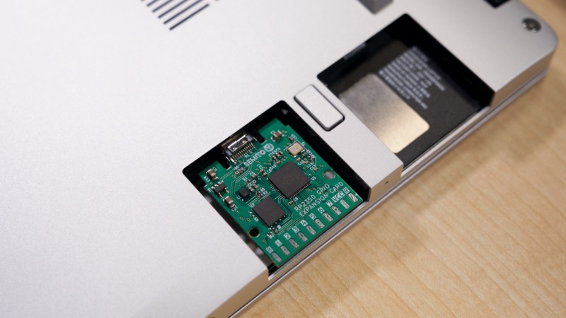
Ever want a microcontroller addon for your laptops? You could do worse than match one of the new and powerful microcontrollers on the block to one of the most addon-friendly laptops, in the way the Framework RP2350 laptop card does it. Plug it in, and you get a heap of USB-connected IO coming out of the side of your laptop – what’s not to love?
The card utilizes the Framework module board space to the fullest extent possible, leaving IO expansion on SMD pads you could marry to a male or female header, your choice. With about seventeen GPIOs, power, and ground, there’s really no limit on what you could add to the side connector – maybe it’d be a logic analyzer buffer, or a breadboard cable, or a flash chip reader, maybe, even an addon to turn it into a pirate version of a Bus Pirate? There’s a fair few RP2350 peripherals available on the side header GPIOs, so sky’s the limit.
Naturally, the card is fully open-source, and even has two versions with two different USB-C plug connectors, we guess, depending on which one is better liked by your PCBA process. Want one? Just send off the files! Last time we saw an addon adding GPIOs to your laptop, it was a Pi Zero put into the optical bay of a Thinkpad, also with an expansion header available on the side – pairing yet another legendary board with a legendary laptop.


“Hmmm… can’t reach this page” Can’t view the project page.
You need to first access the main site of Hackaday.io, sign in and only then click on the link. Even though it does not say that anywhere and the HTTP code is not helpful at all.
CC2 resistor is omitted, placement and routing of L1 and C1/3 is dubious (far away from the MCU, strange long leads to C4/6/7), C4/6/7 are not placed at the MCU pins where they should be. No via stitching leading to semi-islands of +3V3 and long current paths, also swiss cheese effect on GND on bottom layer leading to long current paths. Most zones do not have properly aligned edges (but that’s cosmetical issue). Stackup lists 4 layers, but 2 are unused in the drawing. There’s a net class /GND (inverted GND is probably SKY?). Given how RP2350 is easily subject to instabilities caused by the internal DC/DC, I would be skeptical of stability of this design.
Outline of the PCB is not compatible with the official case model (too large, too thick)
https://github.com/FrameworkComputer/ExpansionCards/tree/main/Mechanical
you can create github issue at https://github.com/semitov/rp2350-gpio-card
Nice.
My monitor is now covered with coffee though.
CC2 resistor is not needed (and in fact would be a big problem for the card’s functioning afaict), since you only need one resistor when wiring to a USB-C plug, unless you also add an emarker to your board or emulate one through PD controller code (but then it’ll be Ra aka 1k). RP2350 dcdc routing should be done well, yeah the distance is a little dodgy, and agreed on all subsequent non-cosmetic points. Also, the official case model is a starting point/reference, no? Unless it claims compatibility with that model. It would be a perfect fit for the card in principle, yeah.
Well unless I’m mistaken it seems the only mechanical fixing for the bare board is the SMD USB plug, if you’re interacting with the IO pins (presumably as there’s no space left to build your peripherals in) that’s not gonna last long.
Actually there is a custom case made for our expansion card by XenoCow, which secures it in place via regular sliding mechanism of Framework expansion cards. Link here: https://www.printables.com/model/1445941-framework-expansion-card-case-for-typec-950-arp24
“CC2 resistor is not needed”
Wrong, both CC1 and CC2 need to be separately pulled down in order for most chargers to recognize the device and give it 5V power. The Framework laptop probably doesn’t care, but that’s still not an excuse to not adhere to the USB C spec. Funnily enough, early Raspberry Pi 4 boards were guilty of this too.
CC2 is needed for a USB-C receptable, but not for a USB-C plug.
Ah, I assumed the distinction was between power source and receiver, not male/female plugs. Does that mean that male plug has only one orientation (thus also explaining only one pair of data pins, and CC1 being pulled down while “CC2” is left floating) while the female plug detects the orientation?
So, why the two sets of pins? For most pins, like VBUS and D+ D-, both sets are wired in parallel, and for data pins and CC pins, the cable only connects one of the sides (side A or side B) (even the TX RX pins for USB 3 SuperSpeed below 10Gbps)
Therefore, on a USB device end (UFP), both CC pins have resistors to GND, and power and USB 2 data pins are connected in parallel, so whatever the cable orientation is, everything is connected. For USB 3, the host side (DFP) will detect which pin of CC is pulled, to determine the cable orientation, then switch the SuperSpeed pins to either set of pins (Use the A side if CC1 is detected, or B side if CC2 is detected).
Therefore, there is always only one CC pin with the resistors connected from the host to device, and which one depends on the cable (The cable have one set of contacts unconnected). Since there is no cable here, you only want one resistor on one side.
Thank you for the explanation. I was getting flashbacks to getting improperly wired female USB-C plugs where they either pulled down both CC pins using a single resistor, or omitted the resistor entirely. I understand now that it’s not an issue for male plugs, but it’s honestly all just piling onto my USB-C induced headache.
I do wish though that the original poster explained why there shouldn’t be a CC2 resistor (or the fact that there actually is no CC2 on the male plug) rather than just saying that it would be detrimental.
that makes sense! if you’d like to learn more, there’s an explanation I did two years ago =)
Given how RP2350 is easily subject to instabilities caused by the internal DC/DC, I would be skeptical of stability of this design.
Is it possibel to read up on this issue more? Do you have a link?
I have an rp2350 pcb where it fails to start one out of 10 tries.
Since the program does not start hard to debug the issue. Also it freeze even if I press the reset/run enough times (about 10). So I can rule out the power supply instability (inrush, etc).
Absolute no idea. I even thought maybe I got counterfeit chip…
https://datasheets.raspberrypi.com/rp2350/hardware-design-with-rp2350.pdf section 2.1.
TLDR: they messed up the on-chip DC-DC converter, but it works well enough if the circuit uses a specific layout and set of parts.
RP2354 is now widely available. Getting rid of the external FLASH will free up a lot of space to improve routing.
Hi! Thank you for the honest review. I couldn’t fit C1/3/4/6/7 near to individual pins of the MCU because of the tight placement of components and I couldn’t rearrange everything from scratch because we needed to produce the design until Maker Faire Rome 2025. Design is actually 2 layers. 4 layers are created by kicad while I was designing, i don’t remember why. I deleted them manually before sending the design to NextPCB. Also for the template, NextPCB one is not fully compatible with the official case model due to slightly changed position of holes and different edges that are changed to fit manufacturing standards of the factory, but default Framework one should fit just right. The slight nearing of pads to the border is intentional to give direct open access to the pins.
We have our own 3D case for the card designed by XenoCow: https://www.printables.com/model/1445941-framework-expansion-card-case-for-typec-950-arp24
I have actually tested the board and clock frequency, memory acces, VCC, regular digital and ADC pins all seem to work pretty fine. The project is educational and is made as part of a student team called SemiTO-V. That being said I want to make a commercial (still fully open source) version outside of the team and will definitely take your considerations into account, especially better routing, implementing via stitching and avoiding swiss cheese!
Petr would you look over a board design for me!
deane@blazie.net
If you don’t have a Framework slot, but a m.2 (A or E key) instead, you could do basically the same with this module:
https://hackaday.io/project/199091-rp2040-rp2350-m2-pico
When i want gpio on my bog standard / cheap / buzzword-incompatible / $150 laptop, i use an rp2040 hanging off the usb port. The fact of the matter is that if you’re using GPIO, you’ve already accepted a mess of cables hanging out of the laptop. “Integrating” it into the laptop gives you nothing.
I’m pointing this out because framework is yet another ‘unique’ thing where the main variation is cost. It’s not truly more extensible or more open, but it is truly much more expensive.
Bet you’re fun at parties.
It’s also easily fixable. I actually managed to buy a new keyboard when mine broke, rather than failing twice to source the correct parts when my Lenovo kB broke. Also, I can have 6 usb a sockets one minute and 6 usb c the next. Very useful. A lot of it is open, I can’t see how it’s less open than a Lenovo or a 150 dpe laptop. It’s pricey but also made well.
Makes me think one of the abandoned rabbit holes, “powered USB hub with XIAO SAMD21”, was a good idea/concept.
Because it could easily fake USB things like mouse or whatnot AND have internal GPIOs to drive things with. Maybe not XIAO, though, too few GPIOs, but those are what I have sitting/waiting in a bin, time to use them. Could be MEGA 2560 (also siting in the same bin) switched to 5v rail, same difference. Actually now that I think of it this IS one of the good uses for a spare MEGA.