[Clough42] created a 3D print for a lathe tool and designed in some support to hold the piece on the bed while printing. It worked, but removing the support left unsightly blemishes on the part. A commenter mentioned that the support doesn’t have to exactly touch the part to support it. You can see the results of trying that method in the video below.
In this case [Cloug42] uses Fusion, but the idea would be the same regardless of how you design your parts. Originally, the support piece was built as a single piece along with the target object. However, he changed it to make the object separate from the support structure. That’s only the first step, though. If you import both pieces and print, the result will be the same.
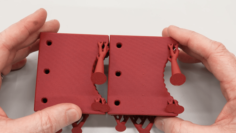
Instead, he split the part into the original two objects that touch but don’t blend together. The result looks good.
We couldn’t help but notice that we do this by mistake when we use alternate materials for support (for example, PETG mixed with PLA or PLA with COPE). Turns out, maybe you don’t have to switch filament to get good results.


Did he print at an angle for mechanical strength reasons?
Yes, it places the layers lines at 45° to the axis of expected work.
Maybe I’m dense, but is this different than the PrusaSlicer support setting named “Top contact Z distance”? You can choose to leave a 0 mm, 0.1 mm, or 0.2 mm airgap between support and object.
I guess that is for automatic support, while he’s choosing the manually define the support?
If I remember that video correctly from my YouTube feed, the type of manually created support isn’t one that any slicer I’ve seen would generate. The slicer for sure wouldn’t know it was support.
I’ve tried something very similar, but it seemed really tedious to build when coupling FreeCad with my feeble CAD skills. I really like the technique and can surely benefit from it, so I need to work on it some more.
There is a slicer that can generate these, it’s called grabcad print, and it’s only for stratasys printers. It’s called a stabilizer there.
Unmmmmmm….
If it doesn’t even touch the side of the print in any way, how does it in any way help?
#physicsrulez
When printing normally layers are extruded close enough that the new hot filament is squirted onto and melts into the warm previous layer, forming a bond. If you leave a gap the new filament just sits on the top without melting together. There’s a balance between the filament not sticking to the support vs the filament sagging and not allowing a good bond for following layers.
I admit I haven’t looked at the video, but many slicers have the option to control the gap between support and the supported layers. I assume there’s some sort of extra magic going on here.
This is not really support gap.
This is better thought of as supports printed horizontally.
So his initial version. Of the supports integrated the support tower into the part by making the walls follow the path of the support tower.
His change was to put a tiny gap between the support tower join and the wall, so the support is now basically connected to the part, but only by the elephant foot effect of the material squishing next to the part wall.
It leave very little impact on the part because the support bridge is better attached to the support tower above and below layers, and less integrated into the wall it is supporting of the real part.
I suspect this method basically only works on angled walls that need support and has basically nothing to do with support z distance, this method is basically NOT a z axis support method.
From the video: it did stuck to the part enough to get lifted from the build plate together with the main part. My guess: it is just enough contact to prevent the part from tipping over mid-print w/o fusing with the main part :shrug:
I need to test this technique with other, stickier materials.
I remember slant3d suggesting these type of supports quite a while ago, he even explains it step by step, the angles, gap etc.
I think some people might get confused by the use of the term ‘support’ in the video. He wasn’t using it to support overhangs, he was using it because he wanted to print the part at a 45 degree angle, but the area touching the build plate was too small to keep it from falling over once it got to a certain layer height, so he designed a support tab to keep it upright. I don’t think any slicer out there currently will do that automatically.
There is a slicer that can generate these, but it’s not automatic, you have to tell it how you want it to be generated. Unfortunately it’s only for stratasys printers.
Mechanical views in Revit are programmed to de-emphasize non-MEP elements. One workaround I’ve found is ensuring the imported geometry is a ‘B-Rep’ solid (like a STEP file) rather than just a mesh.
If anyone is struggling to find or create CAD files for custom equipment, I’ve found that https://ai3dcad.com/ is quite efficient at turning reference images into usable CAD formats like STEP or STL. This allows for better control over materials and visibility overrides in different discipline views compared to standard generic models