Light aircraft often use a heading indicator as a way to know where they’re going. Retired instrumentation engineer [Don Welch] recreated a heading indicator of his own, using cheap off-the-shelf hardware to get the job done.
The heart of the build is a Teensy 4.0 microcontroller. It’s paired with a BNO085 inertial measurement unit (IMU), which combines a 3-axis gyro, 3-axis accelerometer, and 3-axis magnetometer into a single package. [Don] wanted to build a heading indicator that was immune to magnetic disturbances, so ignored the magnetometer readings entirely, using the rest of the IMU data instead.
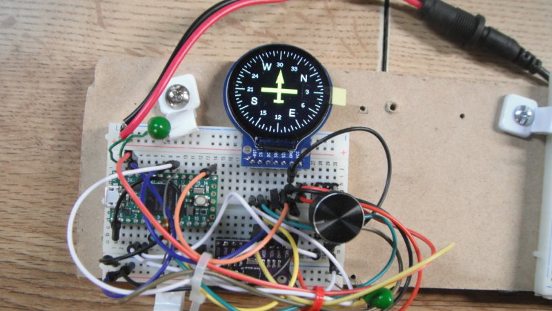
Upon startup, the Teensy 4.0 initializes a small round TFT display, and draws the usual compass rose with North at the top of the display. Any motion after this will update the heading display accordingly, with [Don] noting the IMU has a fast update rate of 200 Hz for excellent motion tracking. The device does not self-calibrate to magnetic North; instead, an encoder can be used to calibrate the device to match a magnetic compass you have on hand. Or, you can just ensure it’s already facing North when you turn it on.
Thanks to the power of the Teensy 4.0 and the rapid updates of the BNO085, the display updates are nicely smooth and responsive. However, [Don] notes that it’s probably not quite an aircraft-spec build. We’ve featured some interesting investigations of just how much you can expect out of MEMS-based sensors like these before, too.


IMU in MEMS have an horrible angular velocity offset noise. It evolves with both temperature, fatigue of the MEMS’s fork (so understand usage of the system), and orientation (meaning that if you calibrate your system on a table, move it on another Euler axis and your offset will differ). Thus, it’s not possible to have an heading sensor that reliable with only MEMS IMU. That’s why there’s a poor compass in the package. The basic idea is for the algorithm to estimate the gyro offset, it can refer to the compass orientation to figure out a wrong (but an order of magnitude more right than integrating the gyro’s speed with a modeled offset subtracted) orientation.
That is, even if you are in a magnetically perturbed area, the idea is that this area will not change much so the long term compass orientation estimation will still be better than the long term gyro orientation.
Also, it’s very common to calibrate the Compass for Hard and Soft iron too (that’s a model you can do once and save it, it’ll be valid for the lifetime of the compass use, unlike the gyro offset) by matching the ellipsoid given by the compass vectors to a sphere.
In the end, estimating the offset of the gyro is the real challenge, and unfortunately is not something you can do without a compass. Even if the accelerometer is possible to use to in a very limited fashion (on the gravity axis it is not possible to calibrate), you need to leave your system to rest so the acceleration measured is g and only g, which is not practical for any system. Also, you can’t rotate a plane on all its axis for remaking your gyro calibration.
Yeah, and where it falls apart is indoor environments where magnetic disturbances vary quickly by area. I once built a robot that loved my fridge, because apparently the magnetic field changes in its vicinity.
The magnetic orientation vector isn’t normalized on this IMU. So you can know if you are in a safe area by just looking at the magnitude of the vector. If it’s not the case, continue integrating the gyroscope for orientation tracking (and use the encoders for the position tracking) until you’re back in the “Earth” magnetic field, where you can almost instantly correct the accumulated error in orientation from the gyroscope. If you cut the compass, you’re simply drifting more and more until it’s completely out of range. BTW, if you are in indoor situation, using BT tags or UWB tags will give you the position and orientation a lot more easily and safely without having to solve large Kalman’s filters models errors.
fields vary continuously. there is no safe cuttoff. there may be no safe area at all indoors.
Or was that just a teenage robot?
Your comments are correct. I have built and tested a 9DOF with magnetometer and it worked quite well except near magnetic objects and motors. (initial calibration was a pain) This BNO085 project was done so I could check out just the gyro portion. I wanted to see how bad the gyro portion really was. That’s also why I put in a 0.5 degree turning threshold so I could try to avoid low level accumulating noise. I also used quaternion math vs Euler to avoid singularity errors. I have yet to do testing and am interested if anyone does do testing with this configuration. BTW aircraft directional gyros also drift over time and typically during level flight I’d just reset the vacuum DG to the compass heading. I was planning on putting this in a RC Tank and the motors would screw up a magnetic compass.
Well done, well thought out. Useful for RC airplanes. :)
Probably better to estimate heading from deltas in GPS locations and combine that with the output of the IMU in a Kalman filter so the GPS gives long term accuracy and the IMU gives information on fast changes.
I’ve played around with doing similar things (or at least similar goals) with a fibre optic gyroscope and 3 dof fluxgate compass (the 6 dof mems gyro/accelerometer).
The fiber optic gyroscope is way better that the mems gyros (at least the ones I could test). Just having the FOG sitting still on the table, you can measure the rotation of the earth, and calculate your latitude (although not which hemisphere you are in).
I bought my FOGs on ebay. They are from industrial robots, but there are even more accurate ones out that are from commercial aircraft navigation systems and various weapons platforms.
Corrector binnacles?