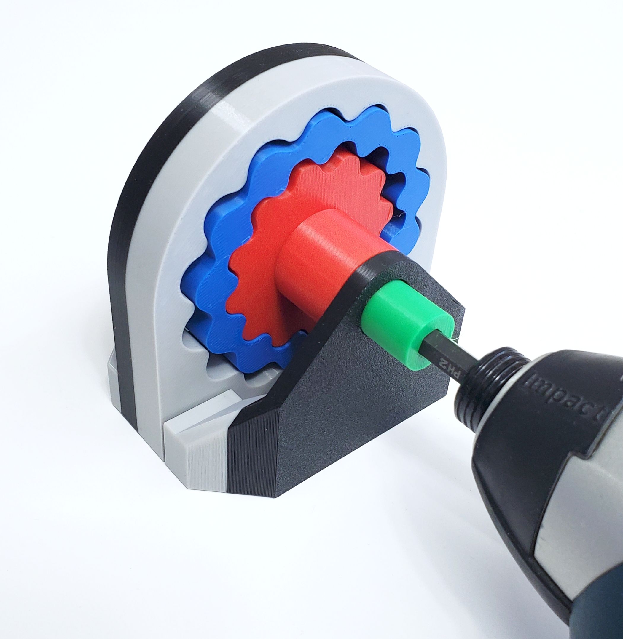
 Cycloidal drives are a type of speed reducer that are significantly more compact than gearboxes, but they still come with a fair number of components. In comparison, the harmonic pin-ring drive that [Raph] recently came across as used in some TQ electric bicycles manages to significantly reduce the number of parts to just two discs. Naturally he had to 3D model his own version for printing a physical model to play with.
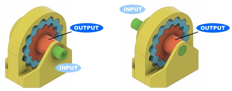
How exactly this pin-ring cycloidal drive works is explained well in the referenced [Pinkbike] article. Traditional cycloidal drives use load pins that help deal with the rather wobbly rotation from the eccentric input, but this makes for bulkier package that’s harder to shrink down. The change here is that the input force is transferred via two teethed discs that are 180° out of sync, thus not only cancelling out the wobble, but also being much more compact.
It appears to be a kind of strain wave gearing, which was first patented in 1957 by C.W. Musser and became famous under the Harmonic Drive name, seeing use by NASA in the Lunar Rover and beyond. Although not new technology by any means, having it get some more well-deserved attention is always worth it. If you want to play with the 3D model yourself, files are available both on GitHub and on MakerWorld.


Looks to be a dual nested cycloidal rather than a strain wave design, as I don’t see anything that’s flexing. Darn clever to get rid of all those load pins, which I’m using currently. After my head stops hurting I’m going to have to build one.
Have a look at the Nabtesco variant. It’s a bit of a hybrid between a planetary gear and a cycloidal gear. Nabtesco has put excentric shafts on the place of the load pins (Which now have normal bearings, instead of the weird sliding contact). And they are driven like the planets in a planetary gear. It’s a really nice combination. Nabtesco makes a whole lot of gear boxes for robot arms.
Original poster, here. You’re correct, this isn’t a strain drive.
I would also have called it dual nested cyclo, except that the patent goes to great length to describe the wave profile’s math, and not call it cycloidal. Although, to me, it looks based on exactly the same principles (eccentric + semi-round pins) as a cyclo. Surely, if they had found a more efficient wave profile they’d have filed a separate patent. So no idea what’s up, hence the care I took not to label anything in this drive as cyclo.
Hopefully someone will be able to help with analysing their described wave profile ?
Update: Built a 31t/30t/29t ring set much like shown in the original video. It turns smoothly – and skips pretty easily. Suspect the axes of rotation of the wobble gear need to be constrained. Also, weirdly, the reduction is exactly half of my original 31t/30t design.
Big plus is around 14 fewer bearings; big minus is half the gear reduction.
Might pursue this a bit further at the expense of an additional bearing to stabilize the wobble gear.
I wonder if the skipping issues could be solved by designing it with two gearsets 180 degrees out of phase the way dual cycloidal drives are setup.
next step, embed coils in the casing and magnets in the blue ring and eliminate the input shaft.
Sounds good. Go for it! Space constraints may be a problem?
yeah I guess you would have to find a sweet spot between size and power to pull it off.
How well does it really deal with vibrations from the excentric movement?
The article mentions the two discs rotate 180° out of phase, but since they have different shapes and mass it seems to me it’s a lot harder to get it balanced, compared to the two identical out of phase discs you put into a cycloidal.
Actually, looking even closer at the construction, only the blue part has excentric movement. The red one is perfectly centered so they do not balance out.
From the cross section image it doesn’t look like you could put in two blue rings that are out of phase either.
Yes you can. This design is stackable.
But it’s likely not necessary if not driving at high rpm. Case in point the HPR-50 motor used on the bike, as shown. Since the pin-ring is so simple, it can be made out of tough industrial plastic and doesn’t weigh much. They didn’t have to cancel out the imbalance in that product. Would likely be the same in robotics joints.
No difference with a cycloidal with 1 pin disc, same imbalance.
Add an out of phase 2nd pin-ring disc and it’s now balanced, like a cycloidal is if an out of phase 2nd pin disc is added.