Modern-day receivers are miracles of digital audio and video processing, but compared to their more analog brethren, they can come with a host of new and fascinating faults. The Onkyo TX-SA806 and SR806 receivers were released back in 2008, with [Tony359] recently getting the latter variant in for repair. Described as having weird digital distortion on the audio outputs, this particular issue got fixed by recapping the PCB with all the digital processing in the first video on this receiver, but this left the second issue unaddressed of a persistent hum, which is the topic of the second video on this repair.
With the easy fix of recapping of the digital board already tried, next was a deep-dive into the receiver’s schematics to figure out where this low-frequency hum was coming from. With it sounding very much like mains frequency hum bleeding through, this was the starting point. Presumably somewhere on the power rails the normal filtering had broken down, so all rails had to be identified and checked for this interference.
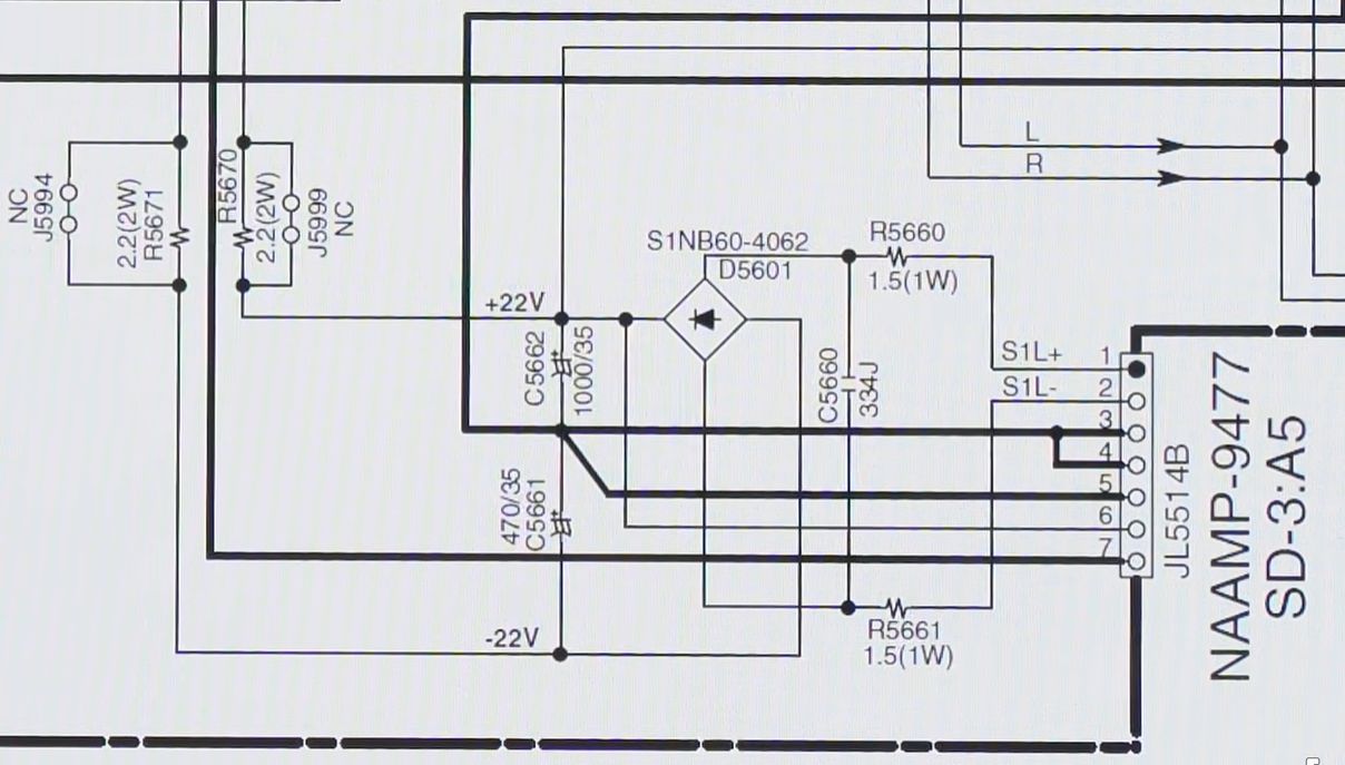
With ripple on the 10V and 12V rails as well as the others seemingly in order, it wasn’t clear where the 100 Hz hum was coming from, but people on the BadCaps forum offered some help. After some back and forth it was deduced that the problem was the +15 VA rail, with heavy ripple on it due to a dead capacitor on the +22 V rail that comes straight from a transformer.
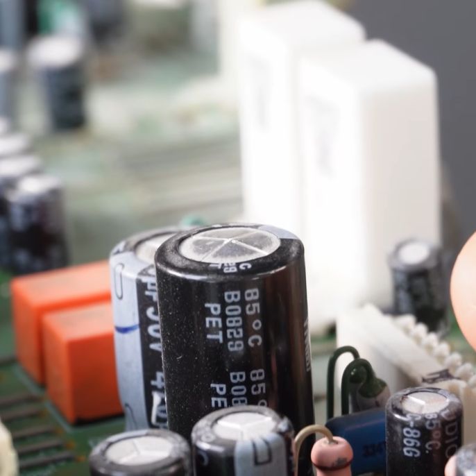
For some reason Onkyo’s engineer and/or bean counters had decided that installing an 85°C electrolytic capacitor on the opposite PCB side of a bridge rectifier was a genius idea, which turned out to be not quite the case. With the capacitor eventually giving up on life, the mains hum was allowed to freely pass onto the analog voltage rail and from there into the outputs.
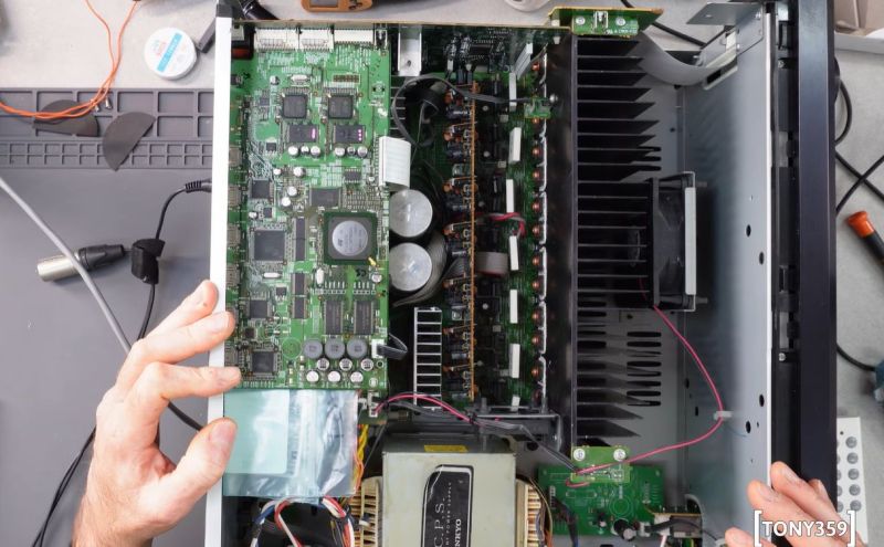
Of course, getting to the target C5662 capacitor was anything but easy, as these modern receivers are tightly packed sandwiches of PCBs, requiring basically a full disassembly. Upon getting to C5662 it was clear that the capacitor was bad, being visibly bulged. Despite being a quality Japanese Nichicon capacitor, such an abusive environment was simply too much. With more similarly poorly spec’ed capacitors at risk of the same fate, these were all replaced with 105°C rated electrolytics.
Perhaps unsurprisingly this fixed the mains hum on the outputs, returning this receiver back to full functionality. In some ways it’s good to know that even with these modern receivers the most typical fault is still due to electrolytic capacitors.


This seems like an excellent argument for the modularization of equipment that performs sophisticated tasks.
The problem with this amplifier (besides the quality) is that due to it’s size, it has a low WAF score (Wife Acceptance Factor). Requiring to buy a bunch more devices to make a combination so it’s modular, reduces the WAF score even further, which will be a disaster for Onkyo that’s cheaping out on important parts.
I modded my Onkyo already with fans to cool down parts as it otherwise overheats. I was able to buy it cheap but it’s really not worth it.
Interesting video.
I have a genuine question about ripple measurements. By using an oscilloscope probe with the long clipable ground lead, don’t you create like an antenna that picks up RF noise? I think i’ve read somewhere you should use the kind of spring you put directly around probe tips.
Same, when he is measuring ripple at 8:12 he has clipped a test lead, which happens to be just above a 125V fuse. I would think it is an even bigger RF noise source, so worsening the ripple measurement, am i wrong?
Asked differrently, what would be the best procedure for such measuments?
Also, to remove some capacitor, he had to remove some silicon like substance which i think is here to prevent vibrations. Or is it for other need? Anyway, wouldn’t it have been better to re-use the same type of silicon paste (acetic acid free type i think)? What could be the consequences of not using it?
And at 23:51, he says that Panasonic FR are the best you can get, and i was wondering why.
I’ve found this thread, and it seems that it is true for a SMPS, but not really for audio devices: https://www.eevblog.com/forum/repair/availability-of-panasonic-fr-caps/
Interesting questions. As to “what would be the best procedure for such measurements?”, I have no idea, lol. I suppose this choice exemplifies “repair guy” vs “electrical engineer”. Whether the 125V fuse causes more noise is a bit moot, as his procedure fixed the hum, and “fixin’ what ain’t broke” lies the way to madness! The thread you cite does show Panasonic FR are not the best for audio equipment and why; obviously their reputation from SMPS has spilled over, thank you for clearing up the confusion. But, your comment is rather relentless in picking apart the videos, and I’m wondering why you aren’t just calling it out as such, instead of just asking questions. I guess we could discuss the pros and cons of silicon paste in this thread, but are we implying Tony359 is a bit of a hack, or just a hacker? lol
May be not being a native english speaker makes the “tone” felt by my questions different that i wanted to (and i’m not even sure that this sentence is really translating well what i want to say!). Sorry about that.
I’ve picked up parts of the video where i was asking myself questions without either having the answer at all, or being sure of having the right answer. So asking questions is not = criticizing, but trying to understand.
So I’m asking questions because i like to understand things better, and other peoples knowledge is invaluable to make progress.
About the 125V fuse, i also probably have not been clear enough: i was wondering if having a probe with long wires monitoring low level signals (a few hundred of mV) in very close proximity of high voltage part (more or less 100V is suppose) does not distort the measurements.
But now i’m also thinking that it also depends if at this point (fuse) it is AC or DC voltage. Since the default hum was a 50Hz harmonic, having an high voltage signal with a 50Hz base pattern (full sine or rectified) close to the probe could have injected an 50Hz harmonic in the measurements.
But (still thinking “live”) since he also measure again the signal after the repair (using, i suppose, the same probe and the same measurement point), and no more ripple is visible, i now realize that my question was may stupid, and i would not take any offence if someone is commenting it was :-)
Nethertheless i was asking this question because i myself have experimenting some strange results with strange noise with a 50Hz (or harmonic of it) frequencies, and i suspected it was because of the standard probe or very similar extending wire/clip i used that were picking up (not so) nearby main frequency. So i still wonder what would be the best way to do such measurements, especially in the same case (difficult to access measuring point and possibly nearby AC or partially rectified AC high voltage).
About the silicone paste, it is also because i have myself replaced capacitor fixed with this kind of paste that i was wondering if it would be useful to buy some to fix the replacement capacitor. If it is only used to avoid problems in case of rought handling, probably not. But if there’s a risk of audible hum because the component can vibrate itself in synchonisation with its charging/decharging cycle frequency, or if external vibrations can be picked up and transferred into the power supply or audio signal, it would be a good idea to use silicone again. I was wondering if people smarter than me could clarify this.
Same about capacitor series: when i’ve discovered that manufacturers are proposing a dozen or more different series of capacitor, i’ve since always been wondering how to pick the best replacement ones. In certain case, it is simply a matter of size (limited height, or even miniaturized). Otherwise at first i tought that picking the lower ESR, with higher temperature and life expectancy seemed to be the best choice. Until i read that… it depends! Low ESR can apparently sometimes create unwanted oscillation, or other unwanted effects. So hearing it that FR series was the best one was an interesting claim. But if i understood well, low ESR is not so important for low frequencies (here main frequency), and some people also claim that it would modify the sound, which is possible if reacting differently to different frequencies.
So i guess that in the case of this Onkio amplifier, using FR for capacitor in the power supply (not SPMS) sections is of no real use (but doesn’t harm and for a few capacitors doesn’t cost much more), but if replacing other capacitors in the audio section, FR are maybe not a good choice…
“May be not being a native english speaker”
You are doing extremely well.
“I’m asking questions because i like to understand things better, and other peoples knowledge is invaluable to make progress.”
That is commendable. For instant, detailed answers on even the most obscure technical topics, ask a free online AI like Grok.
Why are electrolytic capacitors sometimes anchored with silicone adhesive?
Grok:
Electrolytic capacitors — especially larger radial ones — are sometimes anchored to the PCB with silicone adhesive (often RTV silicone or similar compounds) primarily to provide mechanical reinforcement and protect against vibration, shock, and repeated physical stress.
Here are the main reasons this practice is used:
Prevent solder joint or lead fatigue/breakage
The capacitor body can act like a mass on a spring (the leads), so vibration causes repeated flexing at the solder joints or lead bends. Over time this leads to cracked solder joints, work-hardened & fractured leads, or even the capacitor breaking off the board entirely. The adhesive rigidly couples the capacitor body to the PCB, greatly reducing that motion and the resulting cyclic stress.
High-vibration or high-shock environments
This is especially common in:
Automotive electronics (engine ECUs, amplifiers in vehicles)
Audio equipment (amplifiers, especially guitar amps or pro gear that gets moved/transported)
Industrial equipment
Any product subject to shipping abuse, drops, or constant movement
Damping and compliance advantages
Silicone remains flexible even after curing (unlike rigid epoxies or cyanoacrylates). This helps damp vibration energy and absorb shocks without transferring all the force directly to the solder joints. It also allows for slight thermal expansion/contraction movement without putting excessive strain on the leads — some designs even keep a small air gap under the capacitor for this reason.
Why silicone specifically?
Good long-term adhesion to both the capacitor can (aluminum) and PCB materials
Remains elastic over wide temperature ranges
Excellent resistance to aging and environmental exposure
Neutral-cure (non-acetic) RTV silicones are used in electronics to avoid releasing corrosive acetic acid during curing (acetic-cure silicones smell like vinegar and can damage nearby components over time)
In consumer products without much expected vibration (e.g., desktop power supplies or home hi-fi not moved often), you usually won’t see this extra anchoring. But in any design where reliability under mechanical stress matters, a blob of silicone adhesive is a cheap, effective insurance policy against field failures from mechanical fatigue.
Me again: I suspect any foreseen vibration issue with audio amplifiers would be caused by vibrations induced by speaker output. By the way, I just gave a follow-on request to Grok below that answer and asked it to translate it to French and it did so instantly. It may have given the original answer in French if the question had been asked in French, so you may be able to ask questions in your native language.
Ugh, Onkyo and their cheap capacitors…..
It’s best to just assume any faulty Onkyo needs a complete set of replacement capacitors by default.
It seems someone at that ‘premium’ company reallllyyy liked to save some coin by using underspecced capacitors.
They even released ‘secret’ service bulletins advising service techs to just bulk replace capacitors on entire circuit boards for certain models.
Why did the reply go here when I made it at the top level?
This comment section sucks as much as Onkyo capacitors!
The worst thing is that it’s not specifically this one. Pretty much all Onkyo receivers made in the last 30 years have this issue. Especially the ones with HDMI in/out. Those are the worst.
Going to sell my Onkyo Class AB 7.2 receiver soon as it’s using 140W when in sleep mode. Just need something better that’s not made by Onkyo.
True, but we are dealing with audio frequencies here so that’s not a concern on this specific case.
Yes, you want to keep leads to the test point and ground reference short, close together, and away from large noise sources. However, he’s measuring large signals with a fixed, low frequency waveform. It’s easy to distinguish power supply ripple from interference in this case.
Silicone, not silicon. The purpose is mechanical; in addition to vibration damping, it’s probably there to prevent the capacitor from being ripped out of the PCB during rough shipping. It might also help keep the capacitor in place during assembly.
Sometimes I just bridge a good cap over the suspect cap being of the same or larger size. There is a spark that doesn’t seem to hurt as it’s charged to the voltage. I do discharge before trying on a lower voltage assumed or not. Make the bridge-hum stops-bingo.