What is it about mechanical clocks? Maybe it’s the gears, or the soft tick-tocking that they make? Or maybe it’s the pursuit of implausible mechanical perfection. Combine mechanical clocks with “free” energy harvested from daily temperature and pressure variation, and we’re hooked.
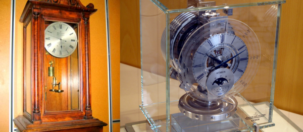
Both the Beverly Clock, built by Arthur Beverly in 1864, and the Atmos series of clocks built between 1929 and 1939, run exclusively on the expansion and contraction of a volume of air (Beverly) or ethyl chloride (Atmos) over the day to wind up the clock via a ratchet. The Beverly Clock was apparently a one-off, and it’s still running today. And with over 500,000 Atmos clocks produced, there must be some out there.
Although we had never heard of it, this basic idea is really old. Clicking through Wikipedia (like you do!) got us to Cox’s Timepiece, which is powered by the movement of 68 kg of mecury under atmospheric pressure. It is currently not running, but housed in the Victoria and Albert Museum in London. Even older is a clock that we couldn’t find any info on that dates from 1620, invented by Cornelius Drebbel. Anyone know anything?
We’ve had energy harvesting on our mind lately, and the article on the Beverly Clock says that it gets 31 μWh over a day when the temperature swings by 3.3 °C. Put into microcontroller perspective, this is 0.39 μA at 3.3 V, so you’ll have to be pretty careful about your sleep modes, and an LED is out of the question. How amazing is it, then, that this can power a mechanical clock?
Thanks [Luke], [hex4def6], and [Wallace Owen] for tipping us off to these in the comment section!
 We’ve probably all experimented with a very clear demonstration of the basic principles of lift: if you’re riding in a car and you put your flattened hand out the window at different angles, your hand will rise and fall like an airplane’s wing, or airfoil. This week’s Retrotechtacular explains exactly how flight is possible through the principles of lift and drag. It’s an Army training documentary from 1941 titled “
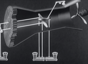
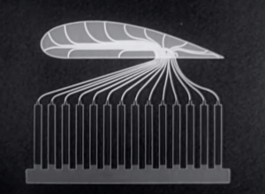 Airfoil models are also unit tested in wind tunnels. They are built with small tubes running along many points of the foil that sit just under the surface. The tubes leave the model at a single point and are connected to a bank of manometer tubes. These tubes compare the pressures acting on the airfoil model to the reference point of atmospheric pressure. The different liquid levels in the manometer tubes give clear proof of the pressure values along the airfoil. These levels are photographed and mapped to a pressure curve. Now, a diagram can be made to show the positive and negative pressures relative to the angle of attack.


