Recently [Bits und Bolts] found himself in a bit of a pickle, when on boot his PC would complain about a connected USB device drawing too much power, before shutting down again. After unplugging various USB devices, the problem was narrowed down to an Elgato Cam Link 4K video capture device.
Some prodding and poking around with a thermal camera on the disassembled device while powered showed that an onboard IC had sprung a power leak. Sadly, even asking nicely, Elgato support wasn’t going to provide board-level repair help, so this was left as an exercise to the owner.
Although the markings on the chip didn’t offer much help, it turns out that this is a more common issue, with a convenient repair guide by [Uldis Melderis] identifying the part as the TI TLV62585 buck regulator.
After purchasing a couple of spares, the defective IC could then be replaced. Following this a quick test showing decidedly less angry electrons. From there it was a matter of reassembling the device in its plastic case and seeing whether the PC was happier with the now hopefully fixed device, which fortunately turned out to be the case.
Any such analysis and repair obviously raises a number of questions, such as why these buck regulators are dying, and why you’re supposed to just toss out a $100 device instead of doing a repair involving a $0.20 part and a few minutes with a hot air gun.
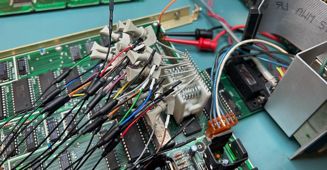
There’s a lot of laboratory equipment out there that the casual hobbyist will never need to use, but that doesn’t mean you wouldn’t snap it up if the price is right. That’s what happened when [Tom Verbeure] saw a 1980s digital delay generator at a flea market for $40. Not only is it an excellent way to learn something about these devices, but it also provides a fascinating opportunity to troubleshoot and hopefully fix it. Such was also the case with this Stanford Research Systems (SRS) DG535 that turned out to be not only broken, but even features an apparently previously triggered self-destruct feature.
These devices are pretty basic, with this specimen incorporating a Z80 MPU in addition to digital and analog components to provide a programmable delay with 12.5 nanosecond resolution on its output channels after the input trigger is sensed. For that reason it was little surprise that the problem with the device was with its supply rails, of which a few were dead or out of spec, along with a burned-out trace.
Where the self-destruct feature comes into play is with the use of current boosting resistors around its linear regulators. Although these provide a current boost over what the regulator can provide, their disadvantages include a tendency towards destruction whenever the load on the supply rail decreases. This could for example occur when you’re debugging an issue and leave some of the PCBs disconnected.
Unsurprisingly, this issue caused the same charred trace to reignite during [Tom]’s first repair attempt, but after working up the courage over the subsequent 18 months the second repair attempt went much better, also helped by the presence of the mostly correct original board schematics.
Ultimately the fixes were relatively modest, involving replacing a discrete diode bridge with an integrated one, fixing the -9 V rail with a bodge wire, and replacing the LCD with its busted AC-powered backlight with a modern one with a LED backlight. Fortunately running the 5 V rail at 7 V for a while seemed to have caused no readily observable damage, nor did flipping connectors because of SRS’ inconsistent ‘standards’ for its connector orientations.
Sadly, when [Tom] emailed SRS to inquire about obtaining an updated schematic for this unit — which is currently still being sold new for $4,495 — he merely got told to send his unit in for repair.
When you’re like [Wes] from Watch Wes Work fame, you don’t have a CNC machine hoarding issue, you just have a healthy interest in going down CNC machine repair rabbit holes. Such too was the case with a recently acquired 2001 Milltronics ML15 lathe, that at first glance appeared to be in pristine condition. Yet despite – or because of – living a cushy life at a college’s workshop, it had a number of serious issues, with a busted Z-axis drive board being the first to be tackled.
The Glentek servo board that caused so much grief. (Credit: Watch Wes Work, YouTube)
The identical servo control board next to it worked fine, so it had to be an issue on the board itself. A quick test showed that the H-bridge IGBTs had suffered the typical fate that IGBTs suffer, violently taking out another IC along with them. Enjoyably, this board by one Glentek Inc. did the rebranding thing of components like said IGBTs, which made tracking down suitable replacements an utter pain that was eased only by the desperate communications on forums which provided some clues. Of course, desoldering and testing one of the good IGBTs on the second board showed the exact type of IGBT to get.
After replacing said IGBTs, as well as an optocoupler and other bits and pieces, the servo board was good as new. Next, the CNC lathe also had a busted optical encoder, an unusable tool post and a number of other smaller and larger issues that required addressing. Along the way the term ‘pin-to-pin compatible’ for a replacement driver IC was also found to mean that you still have to read the full datasheet.
Of the whole ordeal, the Glentek servo board definitely caused the most trouble, with the manufacturer providing incomplete schematics, rebranding parts to make generic replacements very hard to find and overall just going for a design that’s interesting but hard to diagnose and fix. To help out anyone else who got cursed with a Glentek servo board like this, [Wes] has made the board files and related info available in a GitHub repository.
There’s a special kind of satisfaction found in the act of repairing a previously broken device, which is why YouTube is full of repair channels and guides on how to do it yourself. Inspired by this, [Doug Brown] decided to give it a shot himself, with an Elgato HD60 S HDMI capture device as the patient. As per the eBay listing, the device did not show up as a USB device when connected to a computer — a quick probing of the innards revealed that not only were the board voltages being dragged down, but some of the components on the PCB were getting suspiciously hot.
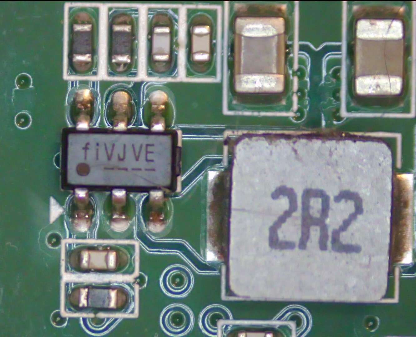
One of the broken switching regulators on the Elgato HD60 S capture device PCB. (Credit: Doug Brown)
On a thermal camera the hot components in question turned out to part of the voltage regulator circuits, one a switching regulator (marked fiVJVE, for Fitipower FP6373A) and another a voltage inverter marked PFNI (Ti TPS60403DBV).
Since both took 5 V, the suspicion was an over-voltage event on the USB side. After replacing the FP6373A and TPS60403 with newly purchased ones, the voltage rails were indeed healthy, and the Elgato sprung to life and could be used for HDMI capture and pass-through. However, the device’s onboard LEDs stubbornly refused to follow the boot-up pattern or show any other color patterns. Was this just a busted Innotech IT1504 LED driver IC?
Swapping it with a pin-compatible Macroblock MB15040 didn’t improve the situation, and the LEDs worked fine when externally controlling the MB15040 on its SPI bus, as well as with the original IT1504. Asking Elgato whether there was a known issue with these status LEDs didn’t lead to anything, so [Doug] decided to tackle the presumed source of the problem: the Nuvoton M031LD2AE MCU that’s supposed to drive the LED driver IC. The PCB helpfully provides a 4-pin JST connector on the board for the MCU’s SWD interface, but Elgato did protect the flash contents, so a straight dump wasn’t going to work.
The binary firmware is however helpfully available from Elgato, with the MCU already running the latest version. This is the point where [Doug] loaded the firmware into Ghidra to begin to understand what exactly this firmware was supposed to be doing. Putting on a fresh MCU with the correct firmware definitely worked, but debugging was hard as the new MCU also enabled protections, so in Ghidra the offending code for this was identified and neutralized, finally allowing for on-chip debugging and leading down another rabbit hole only to find an SPI flash chip at the end.
Ultimately it turned out that all the hardware was working fine. The problem ended up being that the LED patterns stored on the SPI EEPROM had become corrupted, which caused the Nuvoton MCU to skip over them. The same issue was confirmed on a second HD60 S, which makes it seem that this is a common issue with these Elgato capture devices. As a next step [Doug] hopes to figure out a way to more easily fix this issue, as even the streamlined process is still quite convoluted. Whether it is an issue with Elgato’s software or firmware (updater) is unknown at this point, but at least there seems to be a fix for now, even if Elgato support seems to just tell owners to ‘ignore it if capturing works’.
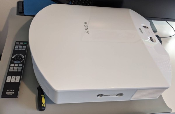
When you’re the proud owner of a beast of a projector like the Sony HW65ES (£2800 in 2016), you are understandably upset when it stops working. In the case of [Wettergren] it appears that a lightning strike in the Summer of 2021 managed to take out the HDMI inputs, with no analog or other input options remaining. Although a new board with the HDMI section would cost 500 €, it couldn’t be purchased separately, and a repair shop quoted 1800 € to repair it, which would be a raw deal. So, left with the e-waste or DIY repair options, [Wettergren] chose the latter.
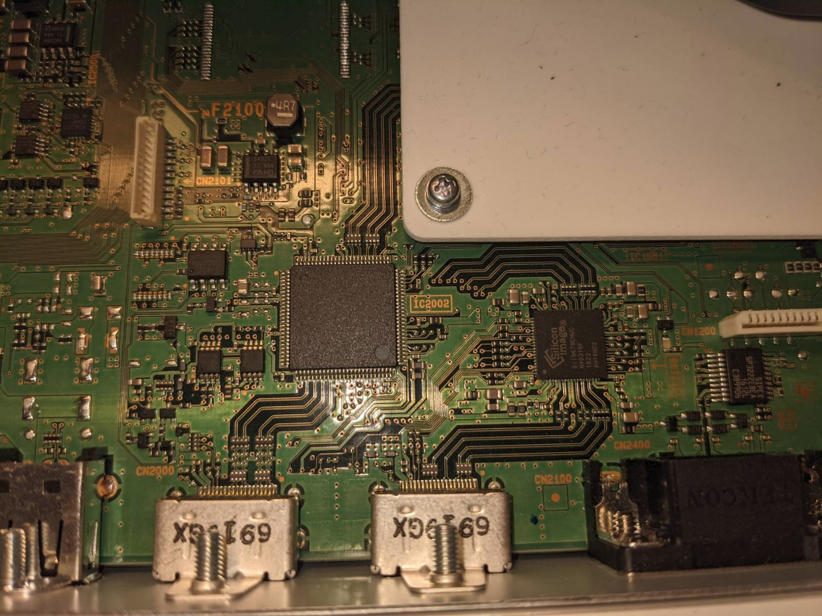
Suffice it to say that taking one of these large projectors apart is rather an adventure, as is extracting the input PCB. On this board some probing showed that while the HDMI 2 port showed some signs of life, with its DDC lines functioning and the EDID readable. The HDMI 1 port had a dead short on these lines, which got traced back to a dead Sil9589CTUC IC, while HDMI was connected to the Sil9679 IC next to it. With this easy part done, the trick was finding replacements for what is decidedly not an off-the-shelf component, but fortunately EBay came through. This just left the slow agony of microsoldering to replace the dead IC, which ultimately succeeded.
After the second repair attempt in May of 2022, the projector is still working in December of 2023, proving that a bit of persistence, a bit of EBay luck and a microsoldering bench with the skills to use it can bring many devices back from the brink to give them a happy second life.

 Recently [Bits und Bolts] found himself in a bit of a pickle, when on boot his PC would complain about a connected USB device drawing too much power, before shutting down again. After unplugging various USB devices, the problem was narrowed down to an Elgato Cam Link 4K video capture device.