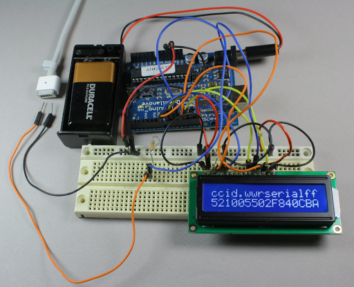
[Ken Shirriff] was interested in how the Apple MagSafe works. Specifically he wanted to know what controlled the LED on the connector itself so he tore one open to see what is inside. There’s a chip present and he didn’t waste time figuring out how the MagSafe communication protocol works.
The DS2413 chip he found on the MagSafe’s tiny little PCB has just six pins. Two of these control a pair of LEDs, which give the indicator its color range. Another pin is used for 1-wire communications. When polled the charger will return a 64-bit identification number that includes a variety of information. [Ken] looks into what data is offered from several different models of charger by using the Arduino setup above. But the results are not entirely straight-forward as he discusses in his article. The 1-wire protocol is also used to switch the LEDs. This process is the responsibility of the computer being charged, but [Ken] shows how the colors can be cycled using an Arduino (with a couple of 9-volts as a source instead of a connection to mains).


