Beefy 100 Amp Electronic Load Uses Two MOSFETs

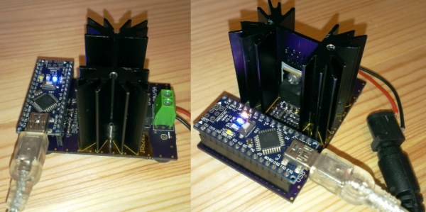
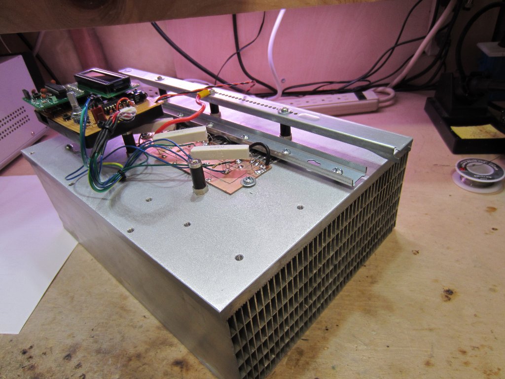
[Kerry Wong] had some extreme MOSFETs (IXTK90N25L2) and decided to create a high current electronic load. The result was a two-channel beast that can handle 50 A per channel. Together, they can sink 400 W and can handle a peak of 1 kW for brief periods. You can see a demo in the video below.

An electronic load is essentially a load resistor you can connect to a source and the resistance is set by an input voltage. So if the load is set to 10 A and you connect it to a 12 V source, the MOSFET should look like a 1.2 ohm resistor. Keep in mind that’s 120 watts–more power than a common incandescent light bulb. So you are going to need to carry some heat away.

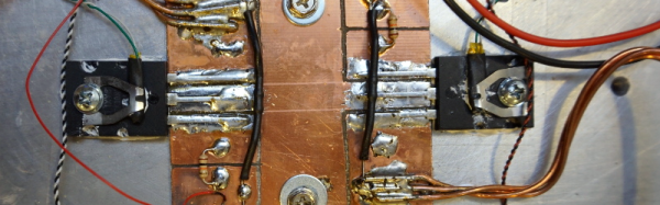
The circuit is pretty simple. The FETs accept a voltage on their gates that sets them to look effectively like a resistor that varies with the voltage. A very small source resistor develops a voltage based on current (only 75 mV for a 50 A draw). That voltage feeds a comparator which generates the gate voltage after looking at the input control voltage. Each millivolt into the comparator translates to an additional 1.33 A through the load.

Continue reading “Beefy 100 Amp Electronic Load Uses Two MOSFETs”

Arduino Electronic Load

A Simple Programmable Electronic Load Using The Arduino

Some projects are both educational and useful. We believe that [Jasper’s] Arduino based electronic load is one of those project.

[Jasper’s] electronic load can not only act as a constant current load, but also as a constant power and constant resistive load as well. The versatile device has been designed for up to 30V, 5A, and 15W. It was based on a constant current source that is controlled by a DAC hooked up to the Arduino. By measuring both the resulting voltage and current of the load, the system can dynamically adapt to achieve constancy. While we have seen other Arduino based constant loads before, [Jasper’s] is very simple and straight forward compartively. [Jasper] also includes both the schematic and Arduino code, making it very easy to reproduce.

There are tons of uses for a voltage controlled current source, and this project is a great way to get started with building one. It is an especially great project for putting together your knowledge of MOSFET theory and opamp theory!

Building A DC Constant Current/Power Electric Load

By just looking at the picture above, we’re pretty sure that most Hackaday readers will have guessed by now that much power can be dissipated by this electric load. For those who don’t know, an electric load (or dummy load) is a device used to simulate a load on a system for testing purposes. This is quite handy when measuring battery capacities or testing power supplies.

The heart of the device that [Kerry] designed is based on 6 power MOSFETs, a few operational amplifiers and an Arduino compatible ATmega328p microcontroller. Sense resistors are used to measure how much current is passing through the MOSFETs (and therefore the load), the MCP4921 Digital to Analog Converter (DAC) from microchip is used to set the current command, and the load’s voltage is measured by the ATmega ADC. Measuring the latter allows a constant power load mode (as power = current * voltage). In his article, [Kerry] shows that he can simulate a load of up to 200W.

Continue reading “Building A DC Constant Current/Power Electric Load”