Having a big block of hot to dump current into is a very useful thing to have if you’re testing batteries, power supplies, high power LEDs, electroplating, or any thing else that would normally require a huge resistor. [Jakub] found himself in need of an electronic load, and instead of a transistor and a pot, decided to make something more automatic: a programmable load built around an Arduino shield.
The idea behind this load is pretty simple: connect a device to a FET and shunt resistor to measure current. Drive the gate of the FET with an op-amp that maintains either constant current or constant voltage. Control everything with a DAC, and you have a programmable load controlled by an Arduino.
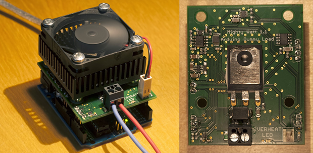
With such a small form factor, getting rid of all that heat was bound to be a problem. For this, [Jakub] is using a 50×50 mm BGA style heat sink with a 5V fan. If it’s good enough for a big CPU, it should be able to handle dumping 70 Watts into a FET. There’s also a conservative application of thermal paste and a very small thermistor underneath the FET that’s able to be read by the Arduino. It might slowly heat up your room, but it’s not going to catch fire.
With the Arduino sketches [Jakub] wrote for his load he was able to characterize a pair of Idea batteries and figure out how much charge a three-year-old recyclable battery had. It’s a great piece of work, and if [Jakub] is willing to go through the hassle of a Kickstarter, it would make a fine crowdfunded product.


Why not slap an atmega on the board itself, instead of attaching it to an arduino ?
Then it wouldn’t be an arduino shield would it? :)
Less hipster creds, but more usefulness. It’s a tough call, I agree.
It’s not about “hipster creds,” you obnoxious cretin. If you want a programmable load cell in a complete package, you can buy one. This one is designed to plug into an existing development board for use in your own projects. That is a useful and sensible route to take.
Of course you can make it standalone, the possibilities are endless. But having some Arduinos always at my hand, I chose to save some money and development time and use the Uno.
In fact, I started with a bigger project – a load with CPU fan (good over 150 W), 12V supply and ATSAM4S ARM processor connected via USB HID. But it turned out to be an overkill for my needs so I made this simpler and smaller version.
The development time isn’t really that much more. You can copy the relevant parts from the Arduino schematics. The atmega chip itself is only a few bucks. Compared to the cost of the PCB and the other components, it doesn’t seem to be a deal breaker.
Also, the development time is a one-time investment. For a next project, you can just copy & paste what you have.
A better idea dskl fd
Arduino is just an Atmel development board, some C++ libraries and a bootloader. All normal AVR code, even assembly, will work with Arduino.
Every time someone uses an Arduino in a project there’s the get off my lawn crowd with their mantras: just use an Atmel, back in my day we programmed 8051s in assembly uphill, both ways in the snow and we liked it, why didn’t you just use a 555 timer, etc etc.
Consider that one can get an Arduino mini pro clone which has an Atmega328, an xtal, a reset button, a voltage regulator, supporting passives, male pin headers, a pcb, and pre-assembled for $4 delivered. Given that you get all of that for only one dollar more than just the mcu, I find your argument a bit weak.
Amen
Nice project, what is really cool is if someone wanted to take your work and make it single board system, stand alone system with a keypad and display, or even one that uses bluetooth your have created a good prototype to work from.
Feel free to pick up where I left off :-)
I like PC connection and no controls on the actual device. But that is just my personal preference.
hi jakub! can you help me build one like this? i’d like to make a bigger version around 300W 12-15V input voltage and 20A of current. can you send me schematic and codes for my guidance?thanks!
Nice one, I’m surprised he can get 70 watts out of that heatsink, at least for any appreciable time.
I recently made one about the same size, 50×50, and using what looks like about the same size heatsink, salvaged from an old Socket-7 machine. Anyway, long story short, with just passive cooling, 10 watt is about the limit for constant dissipation, above which my overtemp protection will kick in after a while (at about 65 degrees on the heatsink).
NB: I could probably bump that set point up a bit, but I prefer to not have burny hot things if it can be avoided. And I do have capability for auto fan but just havn’t got one that fits at the moment :)
60c@10w sounds about right for passive cooling, if you add even a small fan expect to see a 5-10x improvement in cooling capacity for small dense heatsinks (they have very little natural convection). If you look at the stock cooler that comes with even a quad core I7 processor there is not much more cooling area that on this heatsink!
FET has the advantage that you can run it at much higher temperatures than PC processor.
I was a bit surprised to get 70 W without any problems. I was hoping for 50. But it is not easy to estimate the junction temperature. From thermal camera, I got 105 °C case temperature @ 70 W (ambient 22 °C) and the thermistor reports 92 °C. I guess the junction temperature is “a couple of” degrees above the case temperature.
And I run it for few hours @ 70 W but the temperature stabilizes after 5–10 minutes. I even measured the time constant (from thermistor data) and it was around 60 seconds.
There is no need to guess, when you know the case temperature, power dissipation, and Theta JC from the datasheet, you *could* calculate what the junction temperature is.
IXTH75N10L2 has Theta JC = 0.31°C/W, so at 70W, its junction temperature is 70W * 0.31°C/W = 22°C higher than case. So it is an order of magnitude more than the “a couple of” degrees you *think*. (Page 2 datasheet: RthJC 0.31 °C/W (Max))
I am not worrying about operating temperature of the rest of your parts, just that at elevated temperature the accuracy would be less.
Sharing ground means that there would be *other* current paths that goes through the PC ground etc. which would interfere with measurements/operation/accuracy of DUT etc.
Actually, you cannot use Rth in this case because I am measurning the temperature underneath the FET, not at the FET-heatsink interface.
Relatively little power is dissipated through the open sides (measured with thermal camera) or the part that lies on the board (measured with thermistor). So the heat flux is lower and hence the difference between case temperature and junction temperature is smaller.
You were the one that said “I got 105 °C case temperature” from the camera… not the side of the package. So basically your measurements cannot accurately tell what the junction temperature is.
That heatsink is like it is rated for a Pentium I. You can certainly pump more power by running the MOSFET hotter, but it would also raise the temperature of the rest of the board. Sampling resistor, reference voltage for the DAC lastly the opamp offset would be affected by the temperature. (temperature coefficient)
So looks like there are no display, keypad which means this is not stand alone and have to be controlled from a PC and shares the same ground connections to the PC. If you are measuring stuff that requires a floating ground, then you are SOL with this setup.
The board temp rises, yes. All the parts are rated at least 85 °C although the board temperature won’t go much over 70 degrees at 70 Watts. I measured the total temperature coefficient for voltage and current and found it to be 20 to 25 ppm per degree. So 50 degrees more, the change was around 0.12%, which is fine for me.
There are no controls on the shield. My plan was to control it over PC (and log data) and I have a windows application for it.
The ground is shared so it is not good for things that require floating ground unless you run it from laptop on batteries. However, the minus is directly connected to the ground via 200 mA PTC fuse so some common-ground things can be tested relatively safely.
Batteries and floating power supplies are the best things to test, although I have tested a common-ground power supply and it ran quite OK.
Put the whole thing in a container of mineral oil.
Why make a mess with oil when air cooling works fine ?
Well Jakub, I’m impressed. I think I’m more impressed by your shield design than the shield function! Way to go, and I’d love to see your name on HaD again.
100 Watts sunk by four 12 volt automotive light bulbs
http://www.instructables.com/files/orig/FFC/83YL/GSUSNEUG/FFC83YLGSUSNEUG.jpg
Nothing to it!
very nice project – good to see what parts you’re using.
First of all. Great idea and great implementation. Capacitive loads on op-amps often give rise to problems, in part because they can reduce the output bandwidth and slew rate, but mainly because the phase lag they produce in the op amp’s feedback loop can cause instability.
This dude got just about everything right.
He used the right FET, he used the right current sense technique. Bingo! Winner!
Very impressive. Obviously not his first power electronics project.
Only thing I’d change is the heatsink, and maybe temperature sensing.
Thanks! I made a lot of mistakes during the development so it didn’t go without problems :-)
The best price/value heatsinks are CPU heatsinks. But that means making the board much bigger and introducing 12 V rail. But any suggestions regarding the heatsink are welcome!
Also, I made a post about what had to be changed during the development (including temperature sensing): http://kaktuscircuits.blogspot.cz/2014/02/mightywatt-lessons-learned.html
FYI someone, whom I assume is Jakub, has created a version 2 of this device and it’s on Tindie.
He has a blog post on it here:
http://kaktuscircuits.blogspot.cz/2014/07/mightywatt-revison-2-now-50-mightier.html
If you like this ELectronic Load, you may also be interested in in this Arduino Electronic Load. Now current settles so fast that it can do pulsed loads. https://www.tindie.com/products/jaspersikken/jaspers-electronic-load-r3/