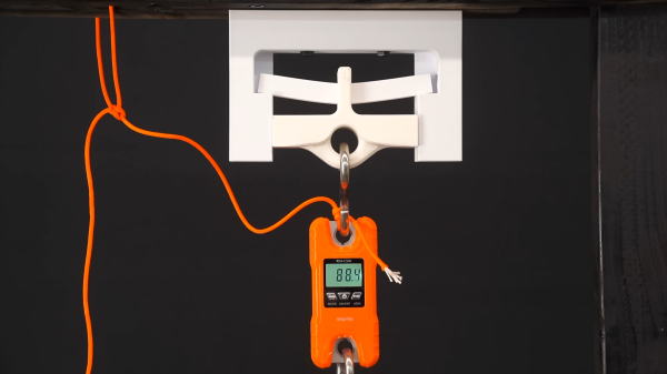
When working with an FDM 3D printer your first prints are likely trinkets where strength is less relevant than surface quality. Later on when attempting more structural prints, the settings become very important, and quite frankly rather bewildering. A few attempts have been made over the years to determine in quantifiable terms, how these settings affect results and here is another such experiment, this time from Youtuber 3DPrinterAcademy looking specifically at the effect of wall count, infill density and the infill pattern upon the strength of a simple beam when subjected to a midpoint load.
When setting up a print, many people will stick to the same few profiles, with a little variety in wall count and infill density, but generally keep things consistent. This works well, up to a point, and that point is when you want to print something significantly different in size, structure or function. The slicer software is usually very helpful in explaining the effect of tweaking the numbers upon how the print is formed, but not too great at explaining the result of this in real life, since it can’t know your application. As far as the slicer is concerned your object is a shape that will be turned into slices, internal spaces, outlines and support structures. It doesn’t know whether you’re making a keyfob or a bearing holder, and cannot help you get the settings right for each application. Perhaps upcoming AI applications will be trained upon all these experimental results and be fed back into the slicing software, but for now, we’ll just have to go with experience and experiment. Continue reading “One Object To Print, But So Many Settings!”


