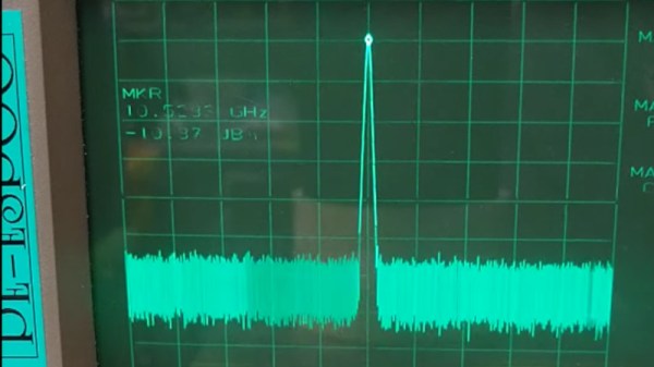
If you’re partial to browsing AliExpress, Banggood, or eBay for unusual hardware, you may have seen the HB100 Doppler Radar modules. These are a PCB with a metal can on board, and their reverse side has a patch antenna array. They work on a frequency of 10.525 GHz, and [OH2FTG] has characterized a few of them to see how close they lie to that figure.
These devices have a superficially very simple circuit that makes extensive use of PCB layout for creating microwave inductors, capacitors, and tuned circuits. There’s a FET oscillator and a diode mixer, and a dielectric resonator coupling the output and input inductors of the FET. This component provides the frequency stability, but its exact frequency depends on what lies within its electric field. Thus the screening can does more than screening, and has a significant effect on the frequency and stability of the oscillator.
The higher quality HB100s have a small tuning screw in the top of the can which in turn adjusts the frequency. This should be tweaked in the factory onto the correct point, but is frequently absent in the cheaper examples. In this case he has a pile of modules, and while surprisingly some are pretty close there are outliers that lie a significant distance away.
If you use an HB100 then the chances are nobody will ever bother you if it’s off-frequency, as its power output is tiny. But it’s worth knowing about their inner workings and also how to adjust them should you ever need to. Meanwhile if you’re interested in Doppler radar, here’s how to design one for a lower frequency.
Continue reading “How On-Frequency Are Those Cheap Radar Modules?”


