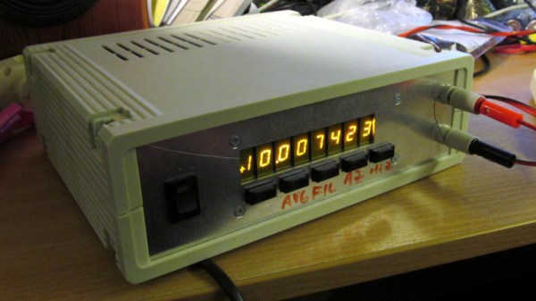
A multimeter is an easy prospect, right? Back in the day you could make one fairly easily with a decent panel meter and a set of precision resistors, and now a digital one can be had for throwaway prices from China.
But what if instead of a cheap-and-cheerful bench instrument your needs extend to a high-precision device, a really good multimeter? It’s a path [jaromir.sukuba] has trodden with his 6.5 digit multimeter project, and along the way he’s offered us a fascinating window into their design that should be of interest to any electronic engineer even if they never intend to build a multimeter.
The range selection network of switches and resistors, microcontroller, and seven-segment displays are universal to a multimeter design, meaning that there is nothing too special about them in a high-precision instrument except that here he’s using an FPGA for timing.
Where the meat lies in this project is in the ADC and its associated voltage reference, and for that he takes a surprising turn. Instead of taking an off-the-shelf ADC part from one of the usual manufacturers, he’s created his ADC from scratch using op-amps, and to understand why that is the case he takes us on a journey into the world of dual-slope integrating ADCs. These circuits are very well explained in a 1989 HP journal article (PDF, page 8), and are a clever design that measures the time taken to charge and discharge a capacitor from the voltage to be measured and compares it to the same time from the reference voltage.
The beauty of it comes out in the HP article, that the mathematics of the charge/discharge cycle cancel out any effects of the analogue component values, allowing the much higher precision of the reference and the clock timing to dictate that of the reading. We look forward to seeing more of this project.
It’s surprising how few home-made multimeters we have on these pages, perhaps because of those cheap ones. Of the few we’ve had, perhaps this state-based Nixie one is most unusual.


