CNC’ed Business Card

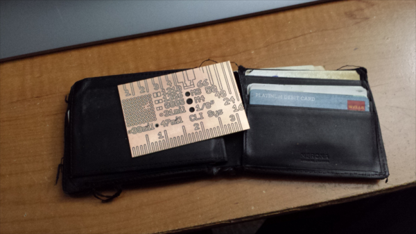
Hobby CNC mills have made rapid prototyping easier and faster for hackers. One really useful application is quickly fabricating your own milled PCB’s. [proto logical] built a Reference PCB Business Card using his CNC mill after repeatedly coming across other hackers who were not too convinced about the capabilities of CNC mills in routing PCB’s (also referred to as isolation milling). He thought of making a business card sized reference PCB to show around when he bumps into such folks.

To keep it useful, he included inch and centimetre scales, 0.1″ grid of holes, reference track widths from 16 mil to 66 mil, a few common drill holes and vias and some SMD foot prints. The single sided board is 50 mil thick, so it doesn’t bulk up his wallet. He’s posted the Eagle board file (direct download) and G-code (text file) for those interested in milling their own reference boards. The idea isn’t new – it’s been tried several times in different form factors in the past, generally using more traditional techniques. [proto logical] got inspiration from [Rohit Gupta’s] TinkerRule – The Maker’s Swiss Army Knife. Then there’s the very popular uRuler made by [Dave Jones] of EEVBlog fame. If you have any suggestions on improving the design, chime in with comments here.

Thanks to [ACG] for sending in this tip that he dug up while looking for CNC routed PCB’s.

Geometry Class Just Got Augmented

ruler

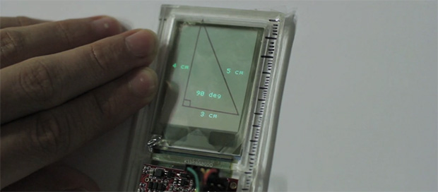
Just about every engineer needs to take a drawing class, but until now we surprisingly haven’t seen electronics thrown into rulers, t-squares, and lead holders. [Anirudh] decided to change that with Glassified. It’s a transparent display embedded in a ruler that is able to capture hand drawn lines. These physical lines can be interacted with or measured, turning a ruler into a bridge between a paper drawing and a digital environment.

For the display, [Anirudh] mounted a transparent TOLED display with a digitizer input into a ruler. The digitizer captures the pen strokes underneath the ruler, and is able to interact with the physical lines, either to calculate the length and angle of lines, or just to bounce a digital ball inside a hand-drawn polygon.

There’s no word on how this display is being driven, or what kind of code is running on it. [Anirudh] said he will have some schematics and code available up on his website soon (it’s a 404 right now).

Gridrunner: A Custom Part For Measuring In Eagle CAD

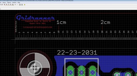
[Koogar] came up with a useful tool for checking the measurements of your layouts in Eagle CAD. He calls it the Gridrunner; a custom part that adds a 200mm ruler to your design. Tick marks are in 1/10th of a millimeter increments for great accuracy when used with the zoom feature of Eagle. Once you’ve got the layout just right, delete the ruler from your design and export it for fabrication. [Koogar] does mention that the beta version of Eagle 6 has a new measuring tool, but he still thinks the Gridrunner offers some things that the built-in tool doesn’t. See just how handy it is in the video after the break. The measuring starts about 1:40 into it.

We found it interesting that [Koogar] is using Eagle for quite a bit more than PCB design. We’ve used it for laying out a drilling template for face plates before, but he’s going far beyond that. He uses the library editor to recreate the parts of his CNC machine which he says are then really easy to align. From there, he exports the CAM files for mounting brackets. Do you use Eagle for something other than PCB design? Let us know about it by leaving a comment. Continue reading “Gridrunner: A Custom Part For Measuring In Eagle CAD”