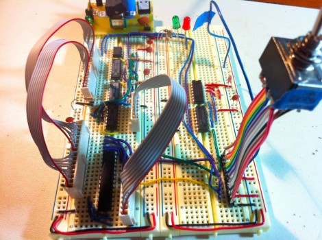
Behold this ATtiny85 based EEPROM programmer. It seems like a roundabout way of doing things, but [Quinn Dunki] wanted to build to her specifications using tools she had on hand. What she came up with is an ATtinyISP USB programmer, pushing data to an ATtiny85, which then programs an EEPROM chip with said data.
The hardware is the next module for her Veronica 6502 computer build. When we last saw that project [Quinn] was planning to add persistent storage for the operating firmware. This will be in the form of an EEPROM programmed with this device. Using ISP and an ATtiny as a go-between means that she should have no problems reflashing the OS without removing the chip. But it all depends on how she designs the interface.
For example, she blew a whole bunch of time troubleshooting the device because garbage data was being written to the chip. In the end, having her manual bus programmer hooked up during the flashing operation was the culprit. Lesson learned, it’s onward and upward with the build.
We’ve been featuring [Quinn’s] projects a lot lately. That’s in part because they’re really interesting, but also because she does such a great job of documenting her experience.


[S]he does such a great job of documenting her exerpience (sic).
I actually made one of these about a week ago as well – used two ‘373 latches and a teensy to do it. Was thinking about posting it. Bit more interesting how she did it, though.
If you can hook up a serial port, you can write bursts of data to the AVR, store it in the AVR’s RAM, then write the whole buffer to the eeprom.
* that is, filling and writing that buffer repeatedly until the eeprom is full.
I’ve always wanted some DIP ribbon cables, what’s the best place to get them like that?
I got those from a guy on eBay who makes them, but All Electronics also sells very similar ones. They’re super useful!
I thought we’d already established, female submissions must be accompanied by a mug shot..? Whatever, just remember for next time.
Very clean build though been there with a very similar face palm moment.
What’s she plugging her ribbon’s into? That looks hella useful.
Maybe breakaway pin headers? You’d have to use ones with spacing that match your breadboard, and find cables that also match that spacing, but what a simple and convenient trick that would be…
I have a ton of ribbon cables with connectors on them, and though they are a bit small the pin spacing is correct, a little brute force and pin headers fit in them fine (though its tough as dried beans to get back out in one piece)
Yeah, I totally dig those ribbon cable headers. I’ve been cutting my ribbons to length and then tinning the ends so I can use them on my breadboards. Headers like that would make it way easier and greatly speed things up.
In a pinch, I’ve been known to stick the tinned ends of ribbon cable in these:
http://www.sparkfun.com/products/10007
That makes for a pretty robust breadboard connection, though not quite as handy as the real connectors.
0.1″ pin headers slot straight into a breadboard (and the connection is improved if you push the pins in slightly so you have about half the pin above and below the plastic block). You can then solder ribbon cable to pin header sockets to make the connectors.
Yah, those are 0.1″ headers connecting the ribbon cables to the breadboard. The trick is they are 10.4mm tall, taller than standard. You need the extra length to seat properly in both the connector and the board. In addition, you have to push on the pins to center them in their plastic retainers so they stick out equally on both sides. I have about 10 of those ribbons, and 10 matching pairs of header dongles. I use them constantly. Can’t recommend them enough.
These:
https://www.jameco.com/webapp/wcs/stores/servlet/ProductDisplay?langId=-1&productId=527654&catalogId=10001&storeId=10001&krypto=9x3mj8umRTpcEpO66oH4KY2YmkL3%2FX4dFbeEUVkTGCoLcQtSFJkrDvSmUdahAKFVhZPMdjiPteQTF9NlRnD7SejhorncNJGV&ddkey=https:StoreCatalogDrillDownView
They’re expensive though, so I only by them for this one purpose, and use normal breakaway headers for everything else.
That is pretty expensive. but worth the convenience.
I feel like I see her name around here a lot.
You (HaD) should have mentioned that this was a *PARALLEL* EEPROM burner. I was staring at the picture wondering what all those wires were for, since most EEPROMs are SPI or I2C (4 to 2 wires!)
You (Quinn) should be able to program modern flash memory chips with essentially the same circuit (and slightly different pre-erase algorithms.) Or “non-volatile SRAM” chips (with a built-in battery.)
Both are still available in DIPs.