Does your home have a security system but you don’t subscribe to the monitoring service to make it work? Rip that baby off of the wall and do something with it, or just build your own system around it. If you have a DSC PC1500RK control panel [CaitSith2] shows us how easy it is to control the buttons, LEDs, and buzzer. If you’ve got a different model this is still a good jumping off point to start your own reverse engineering.
There are only four connections that need to be made. [CaitSith2] is using an Arduino for the demonstration. He connected the red wire to voltage, the black wire to ground, the yellow wire (clock) to digital pin 3 and the green wire (data) to digital pin 2. A communication cycle starts by setting the data line high, then clocking out eight bits to capture keypresses. 16-bits are then clocked in to set the LEDs and drive the buzzer. This is shown in the video after the break as well as documented in his sample code. We’ve embedded the sketch after the break to preserve it in case the pastebin code goes missing in the future.
/*
The code is to interface a DSC PC1500RK alarm keypad.
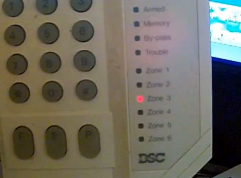
It has 15 keys, 11 LEDs, and a Beeper that can be controlled.
This code cycles through all the LEDs in a top-down fashion.
The beeper is used to acknowledge that a key has been pressed.
If the key was pressed successfully, its character is output on the serial line, at 115200 bps.
Wiring is simple. Red is Vcc, hooked to 5V
Black is Gnd.
Yellow is the Clock line. In this configuration, it is on Digital Pin 3.
Green is Data, and is on Digital Pin 2.
*/
void setup() {
//Pin 2 is Data, and is bidirectional.
//Pin 3 is Clock, and is an output.
pinMode(2, OUTPUT);
pinMode(3, OUTPUT);
Serial.begin(115200);
}
int readdata(int control)
{
int i,j=0,k=control;
int bitcount=0;
for(i=0;i<8;i++)
{
j<<=1;
digitalWrite(2,HIGH);
digitalWrite(3,LOW);
delay(2);
if(digitalRead(2)==HIGH)
j|=1;
digitalWrite(3,HIGH);
delay(2);
}
for(i=0;i<16;i++)
{
if(k&0x8000)
digitalWrite(2,HIGH);
else
digitalWrite(2,LOW);
digitalWrite(3,LOW);
delay(2);
digitalWrite(3,HIGH);
delay(2);
k<<=1; } j^=0xFF; switch(j&0x70) { case 0x10: case 0x20: case 0x40: switch(j&0x8F) { case 0x80: case 0x08: case 0x04: case 0x02: case 0x01: return j; default: return 0; } default: return 0; } return 0; } void printchar(char A, char B, char C, int D) { switch(D) { case 1: Serial.println(C); break; case 2: Serial.println(B); break; case 4: Serial.println(A); break; } } void loop() { int i; static unsigned int j=0x80; static int k=0,l; static int m=0; digitalWrite(13, HIGH); // set the LED on i=readdata(j | l); m++; if(m==4) { m=0; j>>=1;
if(j==4)
j=0x8000;
if(j==0x0200)
j=0x80;
}
if(k==0)
{
switch(i&0x8F)
{
case 0x80:
printchar('F','E','P',(i&0x70)>>4);
break;
case 0x08:
printchar('*','0','#',(i&0x70)>>4);
break;
case 0x04:
printchar('7','8','9',(i&0x70)>>4);
break;
case 0x02:
printchar('4','5','6',(i&0x70)>>4);
break;
case 0x01:
printchar('1','2','3',(i&0x70)>>4);
break;
}
}
if((k!=i)&&(k==0))
l=1;
else
l=0;
k=i;
delay(20);
}
/*
if(Serial.available()) {
int inByte = Serial.read();
if(inByte == 'H')
{
digitalWrite(2,HIGH);
digitalWrite(3,LOW);
delay(3);
}
else
{
digitalWrite(2,LOW);
digitalWrite(3,LOW);
delay(3);
}
if(digitalRead(2)==LOW)
Serial.println("LOW");
else
Serial.println("HIGH");
digitalWrite(3,HIGH);
delay(3);
}
*/


Odds are good there is a central controller that has all the sensors connected to it somewhere. That’s really the box that you should be looking at. The panel is simply an interface to the central controller. Some configurations may have multiple panels, but the brains is all in the central controller.
i CAN CONFIRM THIS (WORK FOR AN ALARM COMPANY) IT’S USUALLY IN A LOCKED BOX
didn’t mean to type in caps,
Dear lord, great project, but does it really need the entire source on the review page? Lol.
I like the idea of posting code here on HAD. I know when lurking in the archives, some links get broken. Maybe add a new section for snippets or something in the forum or on the main blog?
Back on topic: This is pretty nifty, I could see repurposing it for home automation. When I go out of town or will be gone a while I use a PIR motion sensor and a webcam to email images when there is movement detected.
I didn’t gain control to change everything on my alarm, but I was able to just change the call out number instead of monitoring. So if my house calls me while I am away I know the alarm went off and I call the cops and save $200 annually.
How did you change the alarm dial out number? I want to do this since we don’t have monitoring.
I have been eyeing mine to do something similar. Perhaps “enhance” it.
When it comes time to configure DSC systems and the default installer code as listed in the install manuals doesn’t work, an often handy number is 6321. This is more common if the system has a certain blue and white logo added to all the components.
I have updated the code with something that is even more responsive, and now, is controlled by the serial, both in and out.
Input commands by serial, are
1-6 – Controls the Zone 1-6 LEDs
R – Ready LED
A – Armed LED
M – Memory LED
B – By-pass LED
T – Trouble LED.
s – Beep for 2 keypad cycles.
S – Beep for 16 keypad cycles. (All subsequent s/S commands are cumulative.)
Output, is what it says on the keypad, 123456789*0#FEP.
Also, on another note, I do have the main control box for that alarm system as well, and I have confirmed that it is still functional. Bonus to boot, still had its factory default installer code of 1500, and factory default master code of 1234, with no other codes programmed. I do intend to change those codes, if I decide to install that in the future. Dial-out will of course be set up as well, so that I will know if there is a break-in. :)
Always love when electronic stuff is being tossed. That is how I got this stuff.
Updated the code yet again. Max speed the keypad can be read at, is ~30 times a second, which is plenty fast enough for everyday use.
Maybe I might use this in a project of some sort, now that I know how it works. :)
Where is this new code?! Wouldn’t mind having a look.
This is pretty cool. I just bought a house and would like to put in a security system of some sort, but would prefer something under my control rather than monitored (saves money). I thought it’d be cool to use a Raspberry Pi as the base unit to read sensors and control outputs while linking the system to the Internet (sending e-mail/IM messages for system activity, allowing remote arm/disarm via secure login, and possibly tying into home automation with some X10 light/outlet units).
Bah, just connect to the DSC serial port on the alarm motherboard and do everything you want easily with the well documented serial protocol.
Neat hack, but why did he not just go looking for the software that is out there and sniff it’s comms or use the DSC documentation?
Cool I have an old Simon 3 alarm I need to hack so that I get sms messages. I’d never go this deep into it, but it’s good to see someone bravely going down that road.
I love resurrecting these old alarm panels. I know many people who have them and don’t care to replace them, but want some additional functionality and connectivity. For the past several months I’ve been designing a simple interface for logging alarm activations to a webserver and sending email and text message notifications. The device doesn’t have a lot of bells and whistles at this point, but it provides more piece of mind than leaving a system completely unmonitored. It has some commercial potential, but I’ve decided to begin releasing the design under an open source license. I’ve created a ‘DIY’ page and posted the circuit design, firmware source code, and configuration utility source code at http://www.phantomlink.com/diy.aspx. I’ll be posting more details on the dashboard implementation as time permits.
Can’t find the source. Could you send the correct link? Thanks!
We had one of these at our old house. Nobody knew the password so I bought a new motherboard for it off of eBay, It was cheap, didn’t cost much at all. Then I just programmed it to call my cellphone first and to call my in-law’s landline if I don’t answer instead of an alarm company. Of course I couldn’t decode the data by ear to know what sensor was going off but who cares? If the house calls when it should be empty call the police.
I always wanted to throw out that motherboard and just build my own with an Arduino, Pic or something. I just never seemed to have the time and we don’t have that house anymore…
I would like to see commented waveforms of clock and data.
Does he have a web site?
Very cool! I’ve been re-implementing a similar DSC control panel using a JeeNode. I’ve been focusing more on reverse engineering the sensors, but maybe now I can also interface the keypad. Details of my work are here and here.
Your first here link is not linked to anything.
I’m not sure why that link didn’t come through. In any case, here is the first link:
http://sharpk60.blogspot.com/2012/07/reverse-engineering-my-home-security.html
I purchased one of these keypads after reading this article. I have put the code on my arduino, wired the keypad properly, applied power…but all I can get it to do is to buzz/beep this high pitched continuous noise. Does anyone have any suggestions?
matt: I tried this code out with my PC1500RK and it worked without any code changes. It might be that the communication protocol is a little too fast, so you could try increasing some of the delay values in the code. Also, I noticed that the LEDs on the keypad were a little dim so you could try using a higher supply voltage (maybe 9 volts?). I haven’t tried these suggestions so I’m not sure if they will work.
How does this change for aFBII system with 12 zones?
Hmm I have no idea what I could be doing wrong then. I have it wired how the instructions instructed to. All the keypad does after I plug in the arduino uno is buzz and the leds light up. I have even applied a power adapter direct to the keypad thinking that the arduino 5v didnt’ have enough power for the keypad. Even with the power adapter, it just sat there and buzzed with the leds behind the numbers lit up. I just can’t figure it out. I bought it new on ebay and I really wanted this to work.
The hardwired keypads need 12vdc to operate properly, this could be your issue. I do alarm installation and repairs and am very much enjoying this thread.
Controlling the DSC panel with a cheap Arduino over the Internet, for free: http://dsc.juliano.com.br
Has there been any updates to this project? Looking into interfacing to my Ademco Vista 20p panel.
I like this idea Thanks for sharing this ideas with us.
I used this code as a starting point to emulate the keypad and control the actual alarm panel. In addition to emulating the keypad to control the panel, there is also a PGM terminal on the panel that you can monitor in order to determine if the alarm has been triggered, what zones were triggered, etc. I created an Arduino library to keep it simple and the code is available on github: https://github.com/dougkpowers/pc1550-interface
Is it possible to hack the keypad to control a solenoid lock for a hidden door?
I am using a texecom r8 keypad (https://www.grax.co.uk/Upload/SiteImages/XL/b945b594-4bee-4a42-8c04-dc5baa2f49af.jpg) Is there a way to make this one work the same way using you’re sketch?
I am using a texecom r8 alarm system, with a led keypad (https://www.grax.co.uk/Upload/SiteImages/XL/b945b594-4bee-4a42-8c04-dc5baa2f49af.jpg). Is it possible to use you’re sketch on this keypad ? And what do I need to modify?
hello when compiling I get this error (exit status 1
expected unqualified-id before ‘if’) thanks