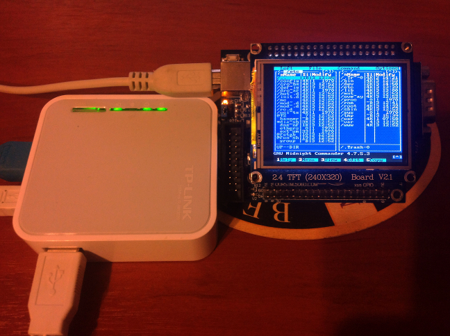
Routers running embedded Linux offer quite a bit of power depending on what you need to do. To extend the usefulness of his TP-Link router [Roman] built a rig that adds an LCD screen to display the terminal. But it ended up being quite a bit more powerful than that.
The first portion of the project was to build a USB video card for the display. [Roman] went with an STM32 development board which resolves the USB device end with the QVGA screen driver (translated). This seems like it would be the lion’s share of the project, but he still needed a driver on the router to interface with the device. This thrust him into the world of USB-class drivers (translated). It even included building graphics support into the kernel of OpenWRT. The final piece of the puzzle was to write a frame buffer (translated) that would help regulate the output to the screen. The result works so well he is even able to play games using ScummVM. See for yourself in the clip after the break.


Woah that’s ridiculous… i am messing with a TFT display as we speak.
Same here! Actually got it drawing a Mandelbrot on it last night
Pretty cool, but why not just use a DisplayLink (USB) monitor? The Linux driver for them has already matured.
Because this board + lcd is about 40$ with shipping
Displaylink is about 140$…
Not to mention bragging rights and epicness of this.
I have always wanted to take a didj or leapfrog explorer and try this.
You can pick them up for almost nothing these days on fleabay. I got my two for £22 each, inc. free delivery.
Cheers, all I could find were Aliexpress items.
Wow, this is seriously awesome ! Kudos on the Kyrandia :)
+1 on AWESOME. FTW!!
This is cool!
Not really related, but I am struggling with the serial port of this (TP-Link 3020) device: When I hook up my teensy to it, I only get a few characters, at most a few screens full, then the serial line freezes. I have used the OpenWrt-suggested Pullup of 10KOhms, of course, but to no avail.
@ausserirdischegesund
I experienced this issue myself. Of course you connected Rx and Tx, and added a pull-up to both lines (if you look at the PCB there are locations for resistors which were omitted). However you must (sometimes) add a ground connection! Sometimes you’ll get lucky and you won’t need it but this is not one of those times.
Find the power supply bypass capacitor – the only largeish one IIRC. If you have a multimeter, use that to determine ground; if not pick the side with the largest plane of copper. Solder on a wire against the cap’s lead, it’s the nicest soldering point for gnd that I found. Hook it up to your teensy’s gnd and you should be good to go.
Note: My device was a 703N not a 3020 but I’m sure the same principle applies.
Best of luck
Typical if if you take ground on the connector shield, which is NOT gnd… Best place is the (relatively) larger round pad near J1 jumper on top side, between USB connect, main chip and PCB printed antenna. Most of the time, pull-ups are not required, except when using FTDI cables.
Wow. this is awesome.
$30 will get you a USB video adapter with dvi.
This hack is truly awesome!
Awesome hack is Awesome
Russians
The first part of this awesome tutorial says: “Those who do not like to solder… so actually we do not have to solder”.
Don’t like to solder? Then f##k your brain with USB. That’s the main idea of this project.
This is freaking awesome. Thankyou!
Incredible project, seems there’s no limit to what you can do with these cheap Linux routers.
Added this awesome hack to openwrt wiki:
http://wiki.openwrt.org/toh/tp-link/tl-wr703n#hardware.mods