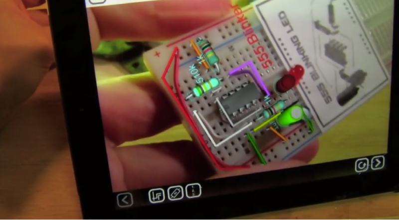
[Scott] sent in this tantalizing view of the what could be the future of bread boarding. His day job is at EquipCodes, where he’s working on augmented reality systems for the industrial sector. Most of EquipCodes augmented reality demos involve large electric motors and power transmission systems. When someone suggested a breadboard demo, [Scott] was able to create a simple 555 led blinker circuit as a proof of concept. The results are stunning. An AR glyph tells the software what circuit it is currently viewing. The software then shows a layout of the circuit. Each component can be selected to bring up further information.
The system also acts as a tutor for first time circuit builders – showing them where each component and wire should go. We couldn’t help but think of our old Radio Shack 150 in 1 circuit kit while watching [Scott] assemble the 555 blinker. A breadboard would be a lot more fun than all those old springs! The “virtual” layout can even be overlayed on real one. Any misplaced components would show up before power is turned on (and the magic smoke escapes).
Now we realize this is just a technology demonstrator. Any circuit to be built would have to exist in the software’s database. Simple editing software like Fritzing could be helpful in this case. We’re also not sure how easy it would be working with a tablet between you and your circuit. A pair of CastAR glasses would definitely come in handy here. Even so, we’re excited by this video and hope that some of this augmented reality technology makes its way into our hands.


Wow, that’s a pretty neat idea. Hopefully people won’t forget that they don’t have it on if it became wearable.
What?
This was really cool!
I hope to see more updates soon
I guess what he means is that if you use augmented reality to try clothes on yourself you should not forget that you aren’t actually wearing them?
Although basically I would guess it’s just a generic comment to get you to click his name so his site has hits.
It’s a thing on techsites that there are a fair number of such fake ‘Wow that is cool, click this’ kind of comments. And this might be one of them.
Wow, that’s cool. I concur, I’d love to see this with a CastAR, but would it work without the retroreflector?
I don’t believe this effect could be achieved with castAR since it can only draw on a reflective surface, like you say. It could draw around the bread board, but not on it. You need something with see-through screens like Meta 1 or Epson’s BT-100 with a camera strapped to it. Google glass is also not really a candidate, since it only draws in the upper corner of the field of view. Here’s a list of a bunch of glasses that _might_ be ready in a year: http://www.imponderablethings.com/2013/09/minority-report-and-terminator-vision.html
Yes, it would work with the true AR attachment.
But then you couldn’t see your hands, unless they can mix in the live stereo video (don’t remember if CastAR has twin cameras). Wonder if you could achieve a translucent VR clip on that would allow overlay gfx on real world view? Have been pondering something along these lines for using CastAR alongside target recognition stuff like Vuforia…
The CastAR true AR attachment has half-silvered mirrors that allows you to still see without using cameras.
To elaborate on what Brian said, the True AR attachment will let you still see stuff in the real world. The VR part of the attachment blocks out the real world, so it’s solely virtual, but that’s not required.
> a translucent VR clip on that would allow overlay gfx on real world view
That is the true AR attachment. You can both see through the glasses to your hands and the real world, and see the projected image. The VR clip on is just another piece that blocks you from seeing the real world part.
Interesting, my first thought is that the holes and outline of the breadboard could determine the position/aspect rather than the placard. Breadboards are pretty standard, it would only need to see a couple edges and a few holes to determine the positioning.
Awesome! A great step for AR.
This really looks like the future of PCB stuffing lines!! If this is an existing product/application I’d love to know about it. Your parts bins could have ID tags and build in logic to identify the right bin for the next part placement. Such a cool idea!! Great project!
Awesome!!
Haha They have a website… My bad.
You work funny. I pick all of my parts before I assemble anything. Pick as you go is a great way to make mistakes.
Except if you work on an assembly line and stuff boards with through hole parts. Sorting sets of parts per board or doing 1 worker – 1 part would be very inefficient.
Being as I worked at a board assembly house I know how it works. Jobs came in in kits, which we would work up, then stuff, solder, final assemble, and inspect. We would do board runs of hundreds, or even thousands of boards. We’d have all of the parts before we’d begin a job too. Boards got stuffed on a table, one part at a time. That is one part would get loaded into multiple boards repetitively. But all parts for a job were on hand, ready to go. Parts were not mixed ever either. We were certainly mass producing, but we did not have an assembly line. Workers had stations, and you’d basically be in your spot all day, every day. Doing essentially the same crap every day too.
We didn’t sort parts, but before we’d run a job we counted them all. Once a job began we were responsible for producing a contracted number of boards. All boards had to have all parts, so we’d better have all parts for all boards!
BTW 1 worker, one part is the most efficient way of doing a job. It is called breaking a job down. That is how mass production works. You do one simple task multiple times.
so how expensive is this solution? and how long does it take to make a layout like the demo shown?
Cool video and quite nice programming, but usually my breadboard are getting so chaotic that this program won’t help much.
Especially if one is doing some analog stuff with multiple opamps (multilayer wire cross connections and wire loop brigdes are common on my breadboard builds) so that this program won’t know which points are connected.
While this is a really cool application of technology, it’s extremely bad for learning about electronics.
It tells you how to attach wires without giving any understanding of how electricity works and no understanding in reading simple schematics and transferring those to the breadboard.
People write schematics in the oddest of ways. I’ve spent hours trying to figure out a schematic without luck and with this simple tool it could have clarified a lot of my questions. So I’m not sure your assessment is right. They don’t (shouldn’t) replace each other.
Bad for learning electronics? As a teacher I can see the value of tools like this one on a starter level. It doesn´t replace the investment in understanding that the student/hobbist has to do in order to make it’s own designs.
Technically it doesn’t tell you how to attach wires, but where to attach them. I have to admit I’ve been using a similar method myself lately designing circuits on computers, then wiring boards up point to point. I don’t think that causes me to know less about electronics. Although it does cause me to take less time to make circuits. I’m not spending a lot of time tracking down mistakes I’ve made either.
So maybe I’m learning less, but I can take the time I’ve saved and learn things the right way.
At the age of 6 I read lines of basic code to my brother (10) from BYTE (et al) magazines . I had no idea what the program did until we debugged it — most of the time it just drew ascii art and/or sang songs. Eventually he moved on and I spent time ‘breaking’ the code to do other things. I am a software architect now because I didn’t need to know proper syntax to appreciate changing a value and getting a result.
I’m currently ‘playing’ with the snap-type electronics kits you can get at radio shack with my 6 year old daughter for the same reason. My main gripe is that it’s so ancient and tedious that it’s hard for even me to follow or be excited about. Ideas like this snap new life into the tedious learning curves that (unfortunately) older experts cling on to as a firewall/ivory tower.
That is so cool! This would be awesome, when I’m gonna learn my kids about electrical circuits :)
Just try to obtain parts that the average hobbyist can breadboard…I was exited to order a sample of TI’s new inductive sensor-then when it arrived, it was so small, there is no way I could use it.
Excellent Work !!!!
Imagine how insanely helpful this would be if, say, you were trying to put together a RAMPS 1.4 or use some other open hardware board and you could scan it and get in-depth information on every IO, resistor, etc?
Man, this should be standard on all OH boards and integrated into a wiki. So many possibilities.
is there any similar augmented projects you guys know of that are opensourced? i’d like to try my hand at the fritzing idea
I made the video shown above. We’re beta testing an app that lets you do 2d graphics (not 3d yet). http://www.equipcodes.com/VisionGuides